Gas detecting method and gas sensors

a gas sensor and detection method technology, applied in the field of gas sensors, can solve the problems of inability to accurately detect the hydrogen concentration in the coexistence of gases, poor responsivity, and long rise time until normal operation of the detector, etc., to achieve the detection of gas leakage upon starting, high gas selectivity, and good accuracy

Inactive Publication Date: 2005-08-25
HITACHI CABLE
View PDF3 Cites 88 Cited by
  • Summary
  • Abstract
  • Description
  • Claims
  • Application Information

AI Technical Summary

Benefits of technology

[0022] According to the invention, detection for the gas leakage upon starting can be attained easily, which was impossible so far in the existent semiconductor type gas detector.
[0023] Further, in the optical detection, a complete explosion proof structure can be obtained easily which enables use in the mode like a densitometer for the process control that was difficult to be applied thereto so far. Further, by the use of a detection film that adsorbs only the specified gas, extremely high gas selectivity is provided and only the gas component intended to be measured can be detected with good accuracy even in a circumstance where various kinds of gases are present together.
[0024] Furthermore, the detection device itself can be decreased in size and reduced in weight and can be mounted easily to portable equipment.

Problems solved by technology

However, since the sensors utilize the catalytic effect, they involve a problem in that the detection portion has always to be kept at a temperature of about 300 to 400° C. In addition, they cannot accurately detect the hydrogen concentration in the coexistence of gases such as methane and carbon monoxide since they have inhibiting effects.
Further, it is also a significant problem in that it takes a long rise time till normal operation of the detector.
However, this involves problems, for example, in that the sensitivity is as low as from several % to several tens % since absorption of light at a specified wavelength is detected and the responsivity is poor.
Further, a method, for example, described in JP-A No. 2002-323441 is also known which forms a thin metal film that adsorbs hydrogen on an optical waveguide channel and optically detects the expansion of the film caused by adsorption; however, close contact with the waveguide channel is poor to result in a problem of lacking in practical usability such as being poor in the reliability as the device.

Method used


Image

  • Gas detecting method and gas sensors
  • Gas detecting method and gas sensors
  • Gas detecting method and gas sensors

Examples


example 1

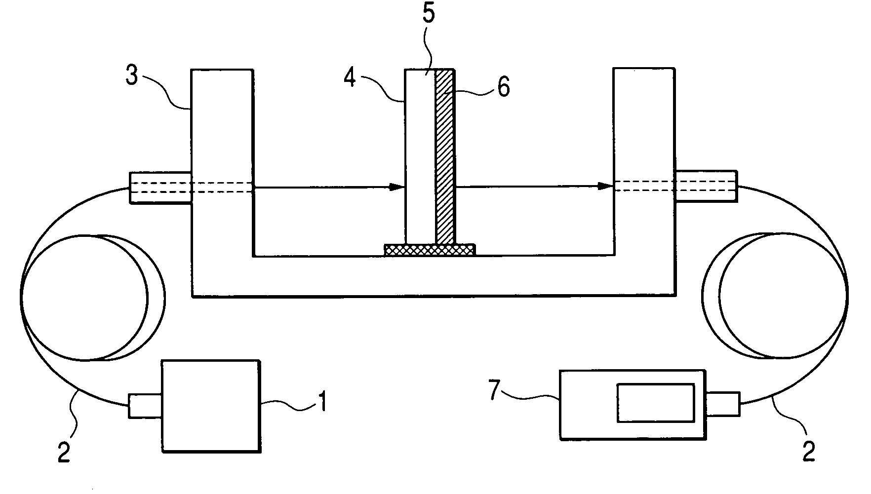
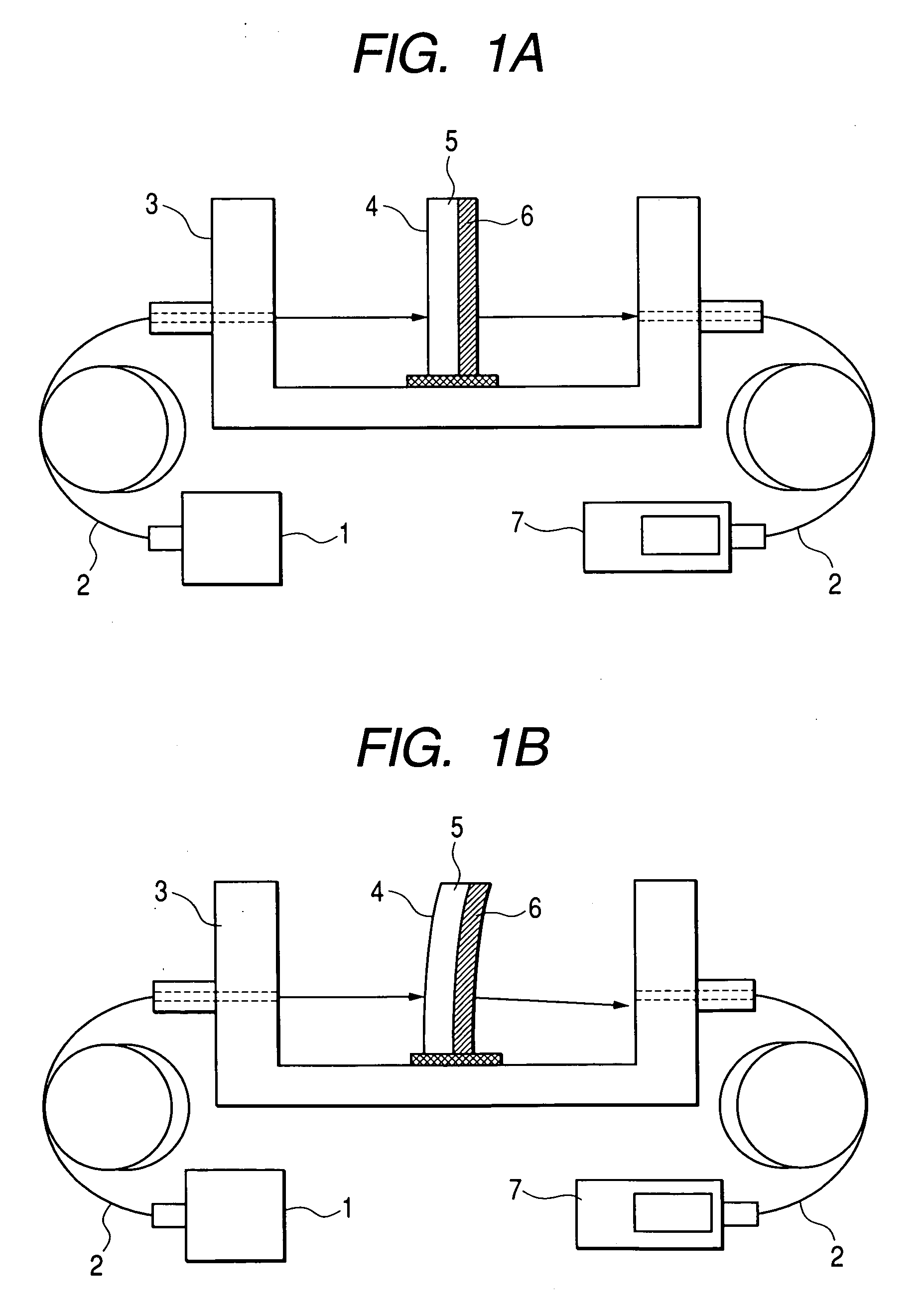
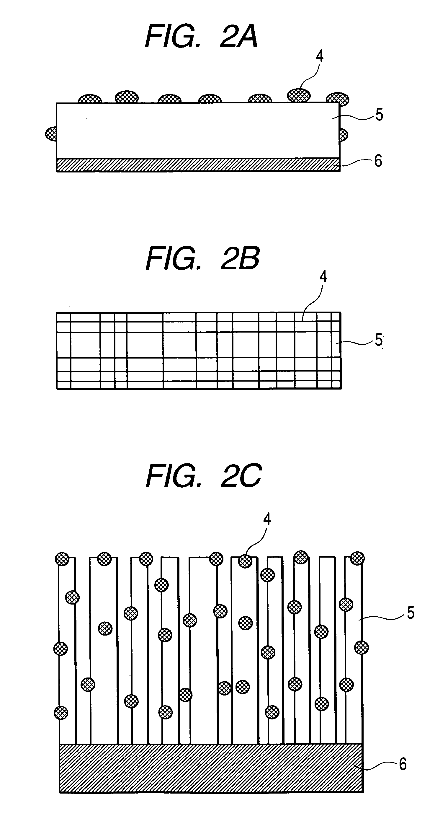
[0081]FIGS. 1A and 1B are cross sectional views of a transmission type gas detection device of a cantilevered structure as an example of the present invention. Light to be detected is introduced from a white light source 1 through an optical fiber 2 into the detection apparatus. Reference numeral 3 denotes a U-shaped light detection block having an optical fiber introduction hole or a coupler positioned accurately in which the introduced light to be detected is introduced by way of a detection film into a fiber on the detection side and detected, for example, by a spectrum analyzer, a photooutput meter, a photodiode or the like as the detector 7. The detection film has a multi-layered structure comprising a catalyst film 4 carried in such a structure not hindering gas adsorption, a gas adsorption layer 5 and a support substrate 6. This example has a cantilevered structure fixed at one end to the U-shaped light detection block 3. For the light detection block, the U-shaped configurat...

example 2

[0085]FIGS. 10A and 10B are cross sectional views of the reflection type gas detection apparatus of a cantilevered structure as an example of the invention. This apparatus has a structure in which the incident fiber and a receiving fiber are identical, but incidence and reception of light may be conducted by independent fibers with no particular problems. The detection light emitted from an LED or white light source 22 passes through a fiber 23 and, by way of an optical circulator 24 and then enters from a detection apparatus casing 21 to a detection film in perpendicular thereto. The detection film has a cantilevered structure and is in contact at one fixed end to the detection apparatus casing 21. The detection film comprises, like in Example 1, a catalyst film 4, an adsorption type detection film 5 and a support substrate 6. In a case of the reflection type, it has a structure of further adding a light reflection layer 25 at the rear face of the support substrate. In a state wher...

example 3

[0087]FIGS. 14A and 14B are cross sectional views of a stress type gas detection apparatus utilizing a piezoelectric element as Example 3 of the invention. The detection film is composed of a multi-layered structure comprising a catalyst film 4, an adsorption type detection film 5, and a support substrate 6 like in Examples 1 and 2, and, for stress detection, a piezoelectric element comprising an upper electrode 41, a piezoelectric film 42 and a lower electrode 43 is further attached to the rear face of the support substrate 6. In a state where the detection gas is not present, the stress is not generated as shown in FIG. 13A, so that the piezoelectric element produces no output. In a state where the detection gas is present, since the gas is adsorbed to the detection film to cause expansion, this results in stress in the multi-layered film, generating an electromotive force from the piezoelectric element. The gas can be detected by measuring the voltage between the first electrode ...


PUM

PropertyMeasurementUnit
temperatureaaaaaaaaaa
diameteraaaaaaaaaa
temperatureaaaaaaaaaa

Abstract

A gas detection method capable of solving the problem with respect to the operation at normal temperature that was impossible so far in the existent catalyst type sensor and detection with high sensitivity that was impossible by the light absorption type sensor. A multi-layered film formed of a first layer adsorbing a specified gas and a second layer having less adsorption are utilized as a detection film, and the detection film is disposed in the direction perpendicular to the optical channel and optically detects the change of stress caused in the detection film by gas adsorption as coupling loss. Alternatively, the stress generated in the detection film caused by gas adsorption is electrically detected by a piezoelectric element or capacitance element.

Description

CLAIM OF PRIORITY [0001] The present application claims priority from Japanese application JP 2004-144726 filed on May 14, 2004 and Japanese application JP 2004-042457 filed on Feb. 19, 2004, the content of which is hereby incorporated by reference into this application. BACKGROUND OF THE INVENTION [0002] 1. Field of the Invention [0003] The present invention relates to a gas sensor for measuring the concentration of a gas and, particularly, it relates to a hydrogen sensor. [0004] 2. Description of the Related Art [0005] For realization of the coming hydrogen energy society, infrastructure building of hydrogen stations, etc. and development for hydrogen-fueled vehicles and fuel cells have been developed vigorously. In a case of utilizing high pressure hydrogen reservoirs for hydrogen-fueled vehicles, in view of serious risk of explosion, every automobile manufacturers adopt safety countermeasure of installing a hydrogen detector at least to one place in each of a residential compart...

Claims


Application Information

Patent Timeline
Patent Type & Authority Applications(United States)
IPC IPC(8): G01N21/00G01N21/75G01N21/77G01N21/78
CPCG01N21/783G01N2021/7793G01N2021/7776G01N2021/7723
Inventor UCHIYAMA, HIROYUKIMOCHIZUKI, KAZUHIROTERANO, AKIHISANAKAMURA, TERUYUKIHONGO, AKIHITOKUMAGAI, TOMOYOSHI
Owner HITACHI CABLE
Why Eureka
Try Eureka