Exposure apparatus mounted with measuring apparatus

a technology of measuring apparatus and exposure apparatus, which is applied in the direction of optical radiation measurement, photomechanical apparatus, instruments, etc., can solve the problems of long measuring time, increase the cost of the entire system, and poor inspection reproducibility, and achieve the effect of short time and simple structur

Inactive Publication Date: 2005-09-01
CANON KK
View PDF20 Cites 27 Cited by
  • Summary
  • Abstract
  • Description
  • Claims
  • Application Information

AI Technical Summary

Benefits of technology

[0005] Accordingly, the present invention is directed to an exposure apparatus that is mounted with a measuring apparatus and measures the optical performance (such as a wave front aberration) of a projection optical system with a simple structure and in a short time (or real-time), an exposure method that utilizes the measuring apparatus, and a device manufacturing method using the exposure apparatus.

Problems solved by technology

A conventional method that actually exposes a mask pattern onto a wafer, and observes and inspects the resist image using a scanning electron microscope (“SEM”) or another means has a problem in a long time inspection due to the exposure and development, difficult SEM operations, and bad inspection reproducibility due to errors caused by resist applications and developments.
However, the conventional measuring apparatuses still enlarge and increase the cost of the entire system that includes the measuring apparatus and exposure apparatus, and cause a long measuring time.

Method used


Image

  • Exposure apparatus mounted with measuring apparatus
  • Exposure apparatus mounted with measuring apparatus
  • Exposure apparatus mounted with measuring apparatus

Examples


first embodiment

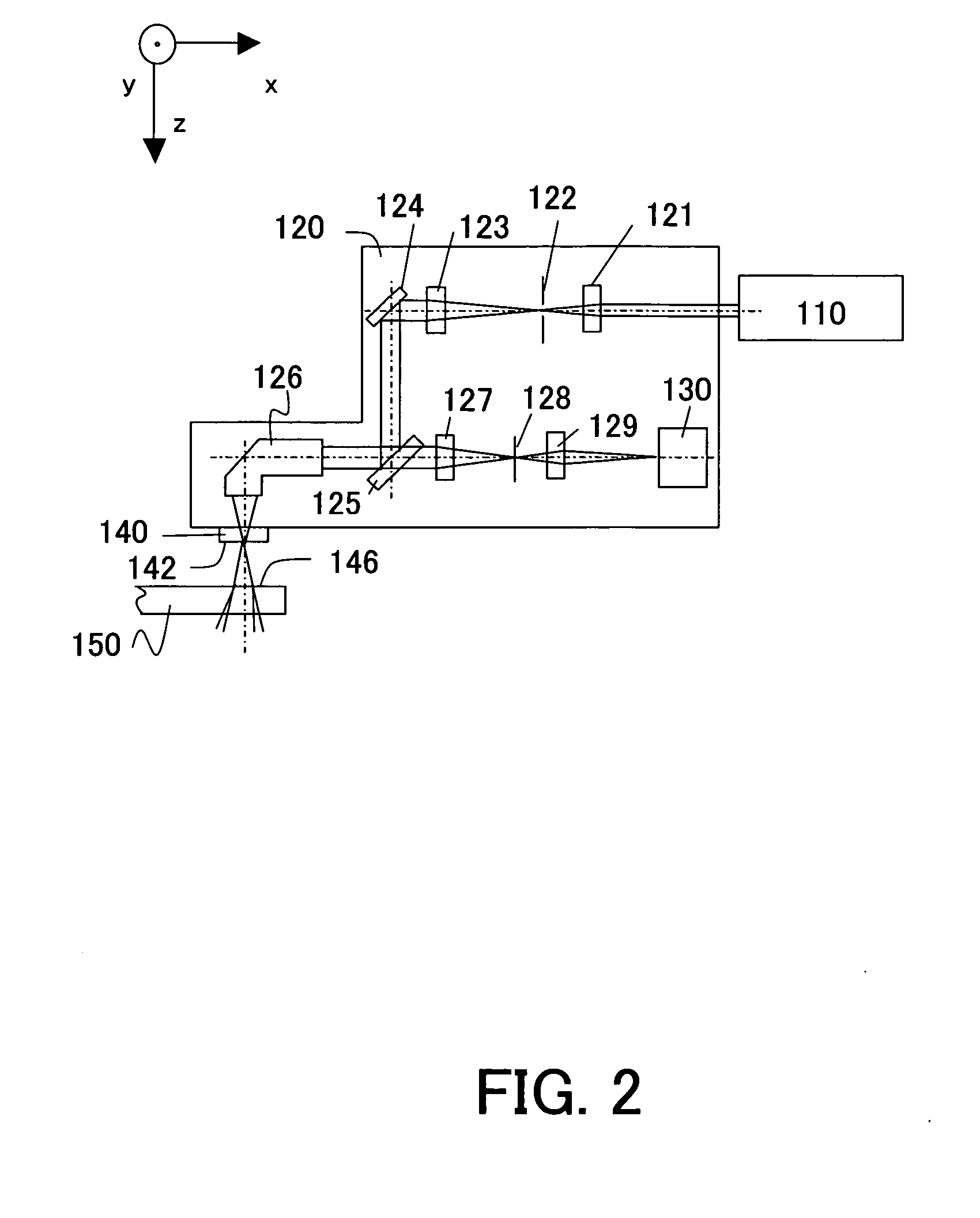
[0072] This embodiment is common to the first embodiment in that the measuring apparatus 101A uses the second illumination apparatus 120A that serves as an alignment scope and simplifies the structure. The optical elements 121 to 130 in the second illumination optical system 120A have similar functions, although a condensing point of the condenser lens 126 is set to the first mask 142A on the mask stage 150.

[0073] The measuring apparatus 101A uses the light splitting means 146 shown in FIG. 4, but is different from the first embodiment in that the light splitting means 146 is provided between the condenser lens 126 and the half mirror 127 in the second illumination optical system 129 shown in FIG. 2 (or uses the second illumination optical system 120A). As a result, plural lights that are amplitude-split by the light splitting means 146 enter the condenser lens 126. The diffraction grating 148a corresponds to the slit 144c and window 145a in the first mask 142A, and the diffraction ...

third embodiment

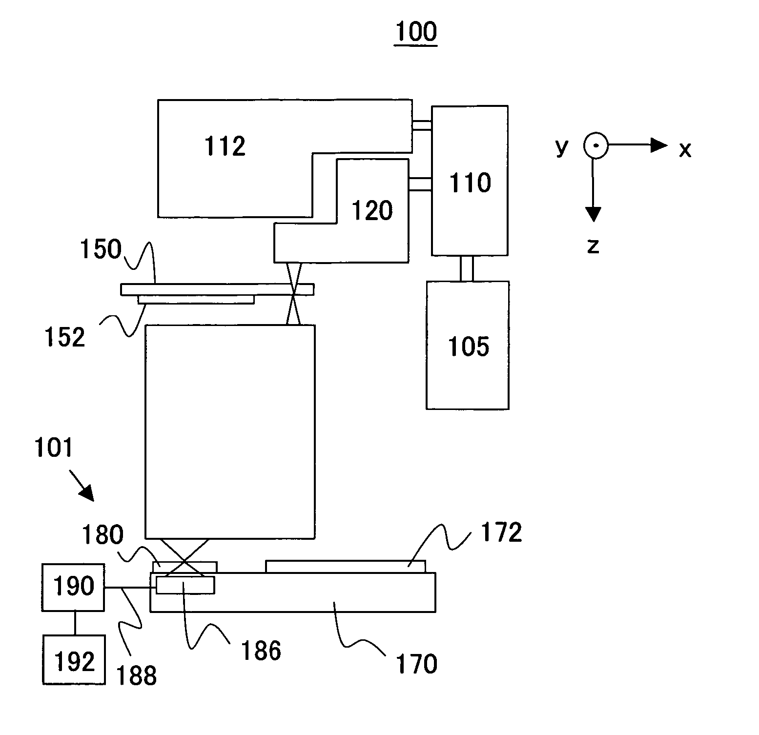
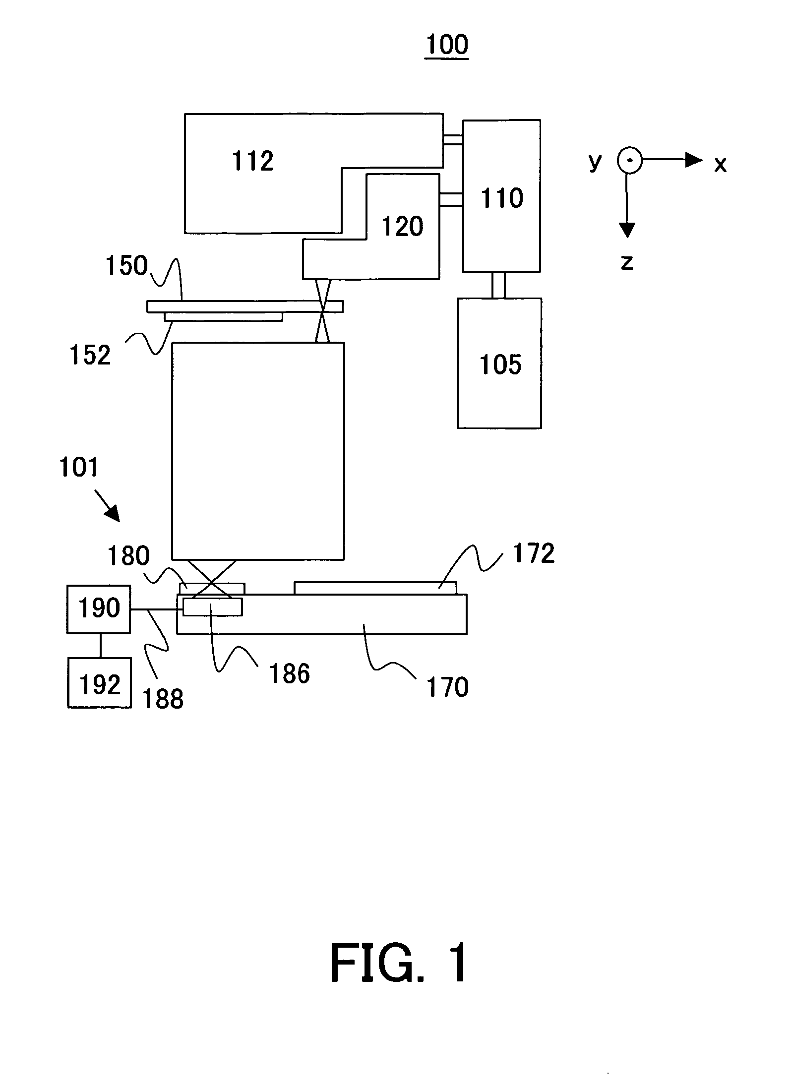
[0084] Referring now to FIGS. 10 and 11, a description will be given of the measuring apparatus 101B according to the present invention. The measuring apparatus 101B differs from the measuring apparatuses 101 and 101A in a first mask 142A and a configuration of a light splitting means 146. Those elements, which are the corresponding elements in FIGS. 2 and 9, are designated by the same reference numerals, and a duplicate description thereof will be omitted. When the measuring apparatus 101B is used, the reference numeral 101 in FIG. 1 is replaced with 101B. Here, FIG. 11 is an optical-path diagram of the second illumination optical system 120, the light splitting means 146 and the first mask 142A in the measuring apparatus 101B.

[0085] This embodiment is common to the first embodiment in that the measuring apparatus 101B uses the second illumination apparatus 120 that serves as an alignment scope and simplifies the structure. The optical elements 121 to 130 in the second illumination...

fourth embodiment

[0117] Referring now to FIG. 14, a description will be given of an operation of the measuring apparatus 101D. First, the wave front aberration of the projection optical system 160 in the x direction is measured (step 1102). Similar to the step 1102 in the fourth embodiment, the light emitted from the light source section 105 is deflected to the second illumination optical system 120 for measuring the imaging performance, via the deflection optical system 110. The light from the deflection optical system 110 is condensed into the optical system 121 for the illumination optical system, and irradiated onto the field stop 122. The field stop 122 has a size enough to irradiate a pattern on the substrate for the first mask 142A, which will be described later. The light from the field stop 122 is collimated by the optical system 123, deflected by the deflection mirror 124 and half mirror 125, and introduced into the condenser lens 126. The condenser lens 126 condenses the light into the ma...


PUM

PropertyMeasurementUnit
wavelengthaaaaaaaaaa
optical performanceaaaaaaaaaa

Abstract

An exposure apparatus for exposing a pattern of a mask onto an object using light from a light source, includes a projection optical system for projecting the pattern onto the object, and a measuring apparatus for measuring, as an interference fringe, optical performance of the projection optical system using the light, wherein the measuring apparatus is a point diffraction interferometer that has a pinhole to form an ideal spherical wave, a line diffraction interferometer that has a slit to form an ideal cylindrical wave or an ideal elliptical wave, or a shearing interferometer that utilizes a shearing interferometry.

Description

BACKGROUND OF THE INVENTION [0001] The present invention relates generally to a method and apparatus for measuring performance of an optical element, and more particularly to an exposure apparatus mounted with a measuring apparatus that measures a wave front aberration of a target optical system, such as a projection optical system that transfers a mask pattern onto an object, and an exposure method and device manufacturing method using the measuring apparatus. [0002] A projection exposure apparatus is used to transfer a pattern on a mask (or a reticle) onto an object to be exposed in manufacturing devices, such as semiconductor devices, e.g., an IC and a LSI, image pickup devices, such as a CCD, display devices, such as a liquid crystal panel, and magnetic heads, in the photolithography process. This exposure apparatus is required to transfer the pattern on the reticle onto the object precisely at a predetermined magnification. For this purpose, it is important to use a projection ...

Claims


Application Information

Patent Timeline
Patent Type & Authority Applications(United States)
IPC IPC(8): G01B9/02G01J9/02G01M11/02G03F7/20H01L21/027
CPCG03F7/706G01J9/02B26B3/02B26B9/00B26B29/025
Inventor NAKAUCHI, AKIHIRO
Owner CANON KK
Why Eureka
Try Eureka