Plasma display panel without injection tip, and method of manufacturing the same

a technology of plasma display panel and injection tip, which is applied in the direction of luminescnet screen, discharge tube, identification means, etc., can solve the problems of conventional neon sign easily broken by an external force, sign using glass tube, excessive size increase, etc., and achieve the effect of reducing the thickness of the plasma display panel, avoiding damage, and reducing the space required

Inactive Publication Date: 2005-09-01
JANG DUK YOUN
View PDF2 Cites 4 Cited by
  • Summary
  • Abstract
  • Description
  • Claims
  • Application Information

AI Technical Summary

Benefits of technology

[0032] Accordingly, the present invention has been made keeping in mind the above problems occurring in the prior art, and an object of the present invention is to provide a plasma display panel and a method of manufacturing the same, which has a structure capable of directly injecting gas into and sealing the plasma display panel, without using any injection tip, thus reducing a thickness of the plasma display panel, reducing a space required to install the plasma display panel in a frame of a neon sign, and avoiding damages, caused by conventional injection tips, while carrying the plasma display panel.

Problems solved by technology

Therefore, the conventional neon sign using the glass tube is problematic in that its size is excessively increased.
In addition to the above-mentioned problem of increasing the size, the conventional neon sign is easily broken by an external force due to structural fragility of the glass tube.
Furthermore, because a voltage more than 1 KV is used as a main power supply, an accident of electric shock may be undesirably caused.
Therefore, the advertisement pattern, which is represented by the glass tube used in the conventional neon sign, must be limited due to the predetermined diameter of the glass tube.
That is, it is almost impossible to form a letter or a pattern of a size smaller than the predetermined diameter of the conventional glass tube.
A size of the letter or pattern represented by the conventional glass tube is also limited.
Although the luminous sign board disclosed in U.S. Pat. No. 4,703,574 provides a luminous sign board with a planar board shape, its structure is complex.
As such, the structure of the conventional luminous sign board disclosed in U.S. Pat. No. 4,703,574 is complex.
Furthermore, because the conventional luminous sign board uses a back light source which is an indirect illumination technique, the fluorescent color of neon is deteriorated.
Therefore, when the conventional electric sign board 10 along with other components is installed at a predetermined position, a space required to install the conventional electric sign board 10 is unexpectedly increased due to the projected part of the injection tip T. That is, the conventional electric sign board 10 with the injection tip T is limited in its installation space.

Method used


Image

  • Plasma display panel without injection tip, and method of manufacturing the same
  • Plasma display panel without injection tip, and method of manufacturing the same
  • Plasma display panel without injection tip, and method of manufacturing the same

Examples


Embodiment Construction

[0045] Hereinafter, embodiments of the present invention will be described in detail with reference to the attached drawings.

[0046] Reference now should be made to the drawings, in which the same reference numerals are used throughout the different drawings to designate the same or similar components.

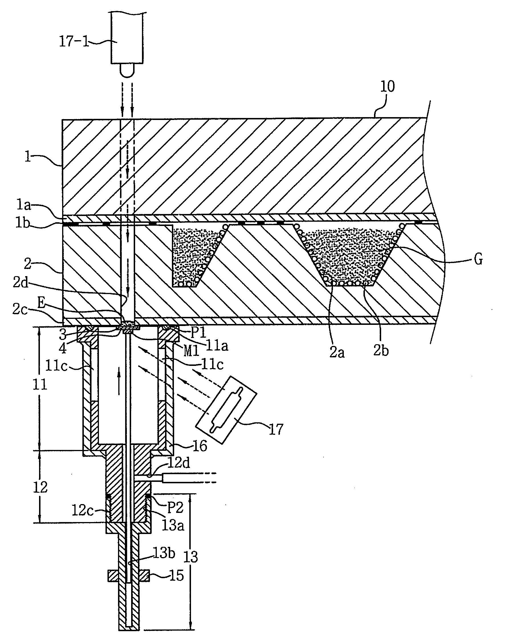
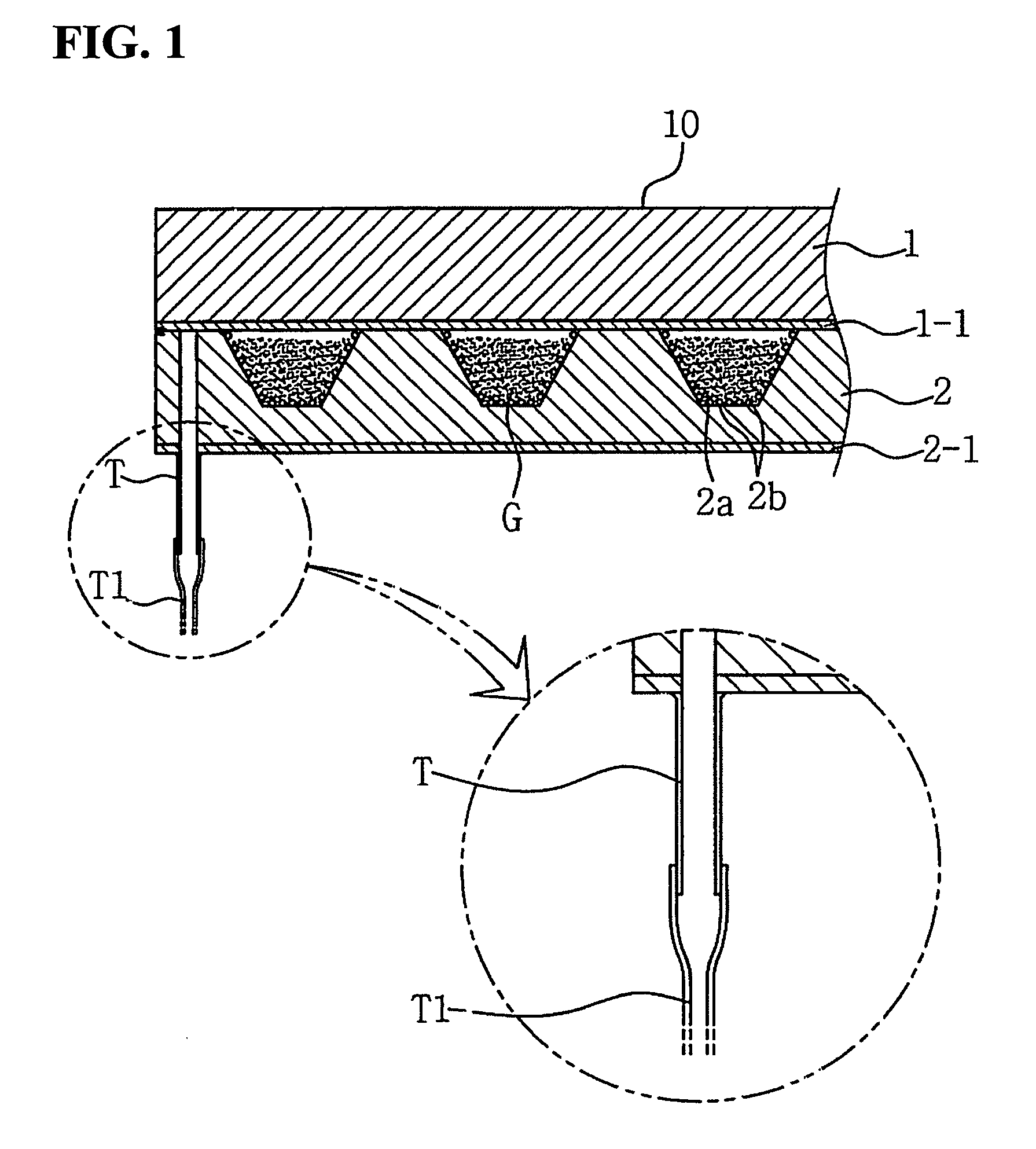
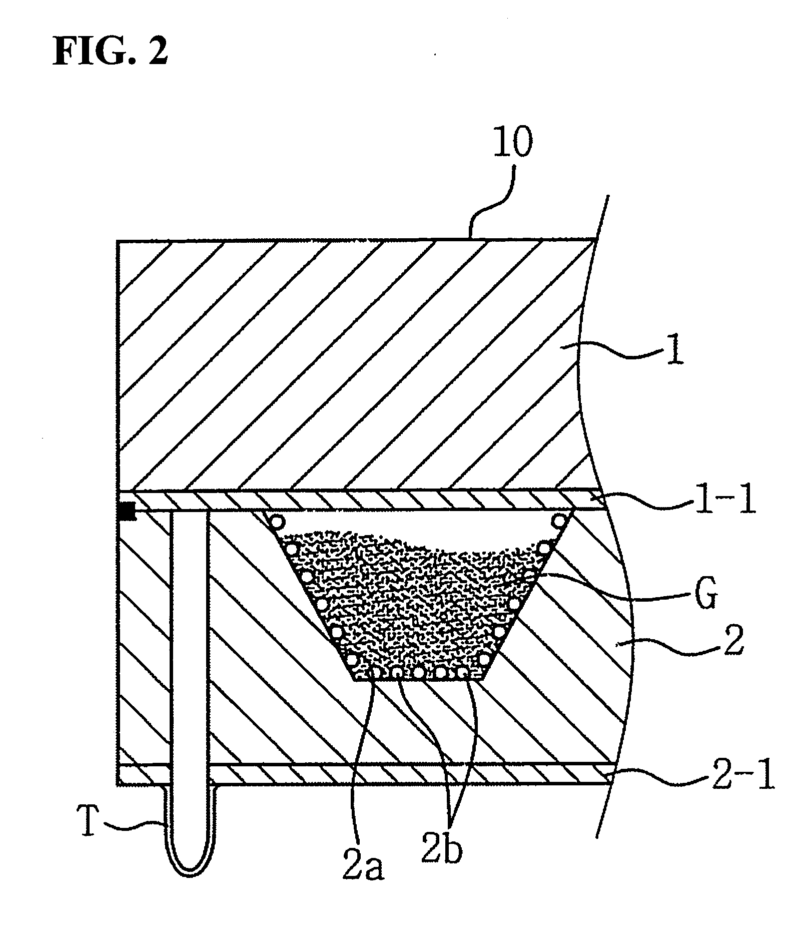
[0047]FIG. 4 is a block diagram showing a process of manufacturing a plasma display panel 10, according to an embodiment of the present invention. Referring to FIG. 4, in a method of manufacturing the plasma display panel 10 of the present invention, a lower glass substrate 2 is provided at step S101, with an electrical discharge cell 2a provided on an upper surface of the lower glass substrate 2 to define a predetermined display pattern of the plasma display panel 10, a fluorescent material 2b applied on a surface of the electrical discharge cell 2a, and a first transparent electrode 2c having a high conductivity and provided on a lower surface of the lower glass substrate 2. Thereaf...


PUM


Abstract

The present invention provides a plasma display panel without any injection tip and a method of manufacturing the same. The plasma display panel without any injection tip has a structure capable of directly injecting gas for electric discharge into the plasma display panel through an injection hole of a lower glass substrate using a vacuum apparatus while manufacturing the plasma display panel, thus sealing the plasma display panel in the vacuum. Therefore, the plasma display panel without any injection tip reduces a thickness thereof, thus reducing a space required to install the plasma display panel. Furthermore, the plasma display panel without any injection tip avoids damages, caused by an injection tip of conventional plasma display panels, during a process of transporting or installing the plasma display panel.

Description

BACKGROUND OF THE INVENTION [0001] 1. Field of the Invention [0002] The present invention relates generally to plasma display panels without injection tips and methods of manufacturing the same, and more particularly, to a plasma display panel without any injection tip and a method of manufacturing the same, which has a structure capable of injecting gas into and sealing the thin plasma display panel, without using any injection tip, while manufacturing the thin plasma display panel, thus stably exhausting air from and injecting the gas into the plasma display panel, reducing a space required to install the plasma display panel in a frame of a neon sign, and avoiding damages, caused by the injection tip of a conventional plasma display panel, while carrying the plasma display panel. [0003] 2. Description of the Related Art [0004] Generally, neon signs are light emitting devices to display letters or pictures (hereinafter, term “advertisement pattern” is used to include all of the de...

Claims


Application Information

Patent Timeline
Patent Type & Authority Applications(United States)
IPC IPC(8): H01J17/20H01J9/00H01J9/24H01J9/385
CPCH01J9/241H01J2217/49264H01J9/385G09F9/313H01J9/24H01J9/38H01J11/10
Inventor JANG, DUK-YOUN
Owner JANG DUK YOUN
Why Eureka
Try Eureka