Computer network architecture and method of providing display data

a computer network and display data technology, applied in data switching networks, instruments, program control, etc., can solve the problems of difficult to connect more than one monitor to a computer, difficult to share monitors between more than one computer, heavy weight and fragile cathode ray tube display, etc., to achieve convenient replacement and optimise the end-to-end system

Inactive Publication Date: 2005-09-01
NEWNHAM TECH INC +1
View PDF6 Cites 96 Cited by
  • Summary
  • Abstract
  • Description
  • Claims
  • Application Information

AI Technical Summary

Benefits of technology

[0015] Ultra-thin client devices are stateless, which means that the device can be rebooted, or easily replaced in case of failure, with no loss to data and minimum reconfiguration. They can be implemented as pure solid-state devices. They need no moving parts, making them more robust, especially in hostile environments. They are furthermore often completely silent in operation.
[0016] The simplicity of ultra thin client devices means that a connected network server can be given a more complete understanding of its internal workings and can use this to optimise the end-to-end system.

Problems solved by technology

Cathode Ray Tube (CRT) based displays are large heavy and fragile, and so users seldom want more than one on their desk.
The electrical requirements of the Video Graphics Array (VGA) cable used to connect the processing device to the display make it bulky and limit its length to a few feet so the monitors need to be in close proximity to the machines driving them.
Typically each computer has only one VGA connection and it is therefore difficult to connect more than one monitor to a computer.
Similarly, it is not easy to share monitors between more than one computer because monitors generally have just one or two inputs.

Method used


Image

  • Computer network architecture and method of providing display data
  • Computer network architecture and method of providing display data
  • Computer network architecture and method of providing display data

Examples


Embodiment Construction

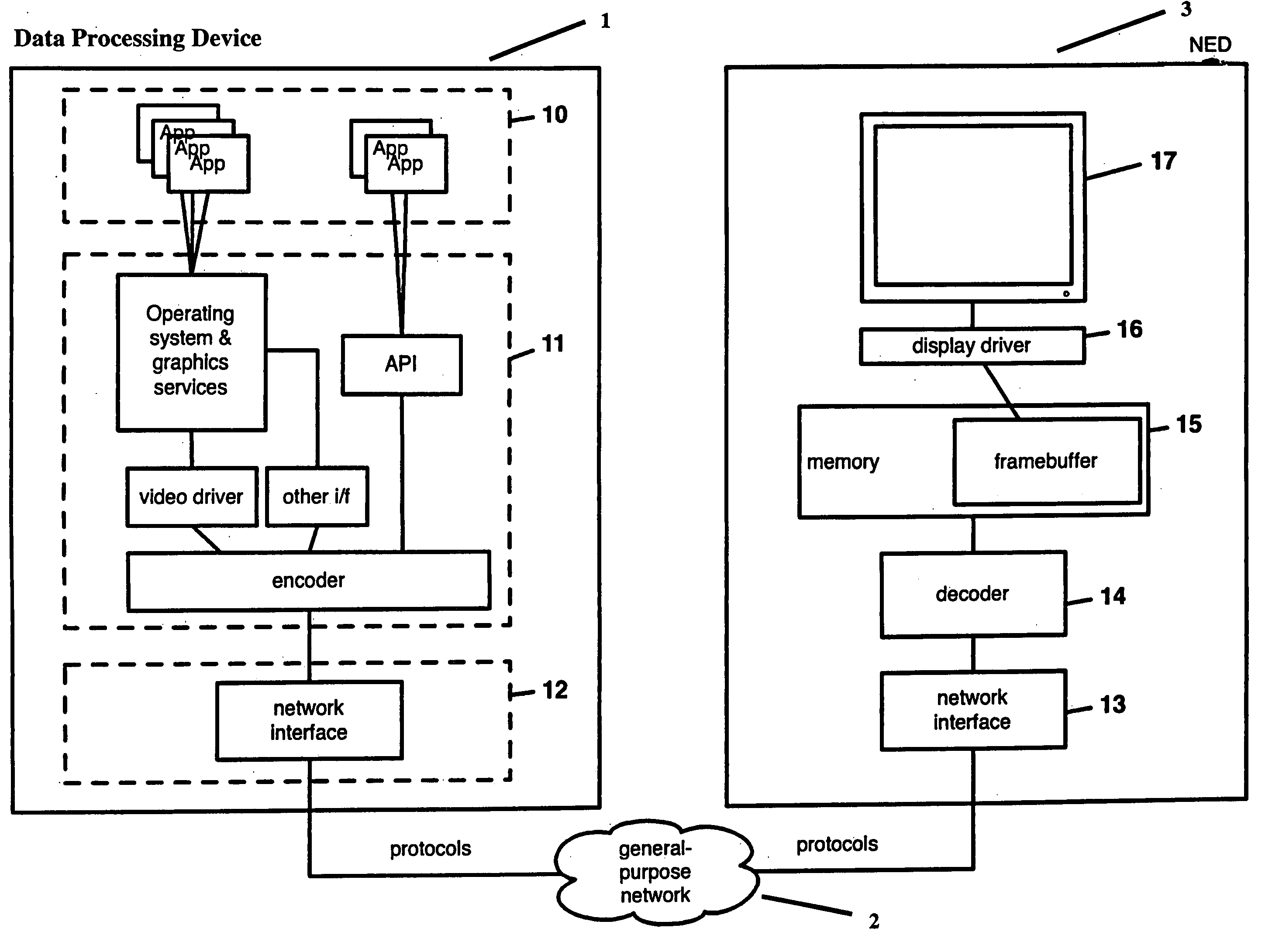
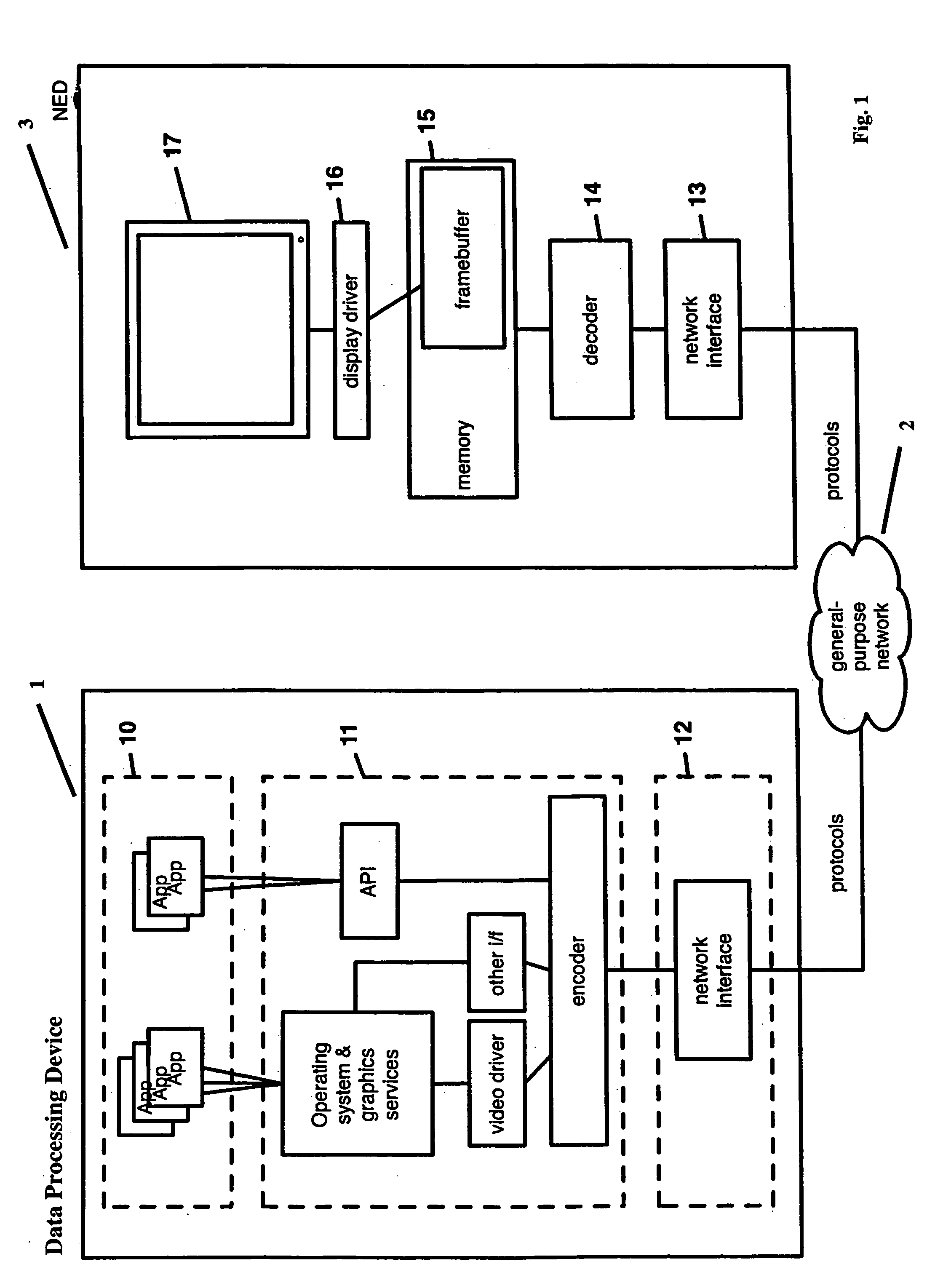
[0055] Referring to FIG. 1, a system in accordance with an embodiment of the present invention has a data processing device 1 (such as a personal computer, laptop or PDA) from which image data is transferred and a display device 3 connected to the data processing device 1 over a network 2. A display device 3 of this sort will hereinafter be referred to as a network enabled display (NED 3).

[0056]FIG. 1 shows a data processing device 1 running applications 10, software and / or hardware components 11 for converting graphical data and a network interface 12. The NED 3 includes a network interface 13, a decoder 14, a memory 15 and display driver 16, as well as a display screen 17.

[0057] A recent trend in the field of electronics devices has been the introduction of a new class of very simple network-connected devices, sometimes referred to as ‘ultra-thin devices’ or ‘ultra-thin clients’. The name comes from a comparison with more traditional networked devices—computers or large peripher...


PUM


Abstract

A display system in which one or more display devices are arranged to be addressed by a data processing device (e.g. a laptop computer) coupled to the display devices over a general purposes data network, thereby providing an ultra-thin network-connected display. The image data transmitted the display devices directly represents an image to be displayed on the display devices. In one embodiment the system includes an adaptor which couples a conventional display device to the network, thereby delivering the display data directly to the display device over the network. In an alternative configuration, the system includes a network-enabled monitor, which incorporates ultra-thin client componentry. Both embodiments dispense with the limitations imposed by dedicated VGA cables. Display devices addressed by the data processing device can thus be placed at great distances from the data processing device, and from one another. Wireless networks are also contemplated.

Description

CROSS-REFERENCE TO RELATED APPLICATION [0001] This application claims the benefit claims the benefit of U.S. Provisional Application Ser. No. 60 / 548,487, filed Feb. 27, 2004, which is incorporated herein by reference.FIELD OF THE INVENTION [0002] The present invention relates to computer network architectures and the provision of display data to display devices. BACKGROUND TO THE INVENTION [0003] The personal computer, as most people think of it today, consists of a display, a processing unit and some input and output devices, typically a keyboard and a mouse. [0004] In some embodiments, these units are combined into a single device, a laptop being the most obvious example. However, the majority of computers sitting in offices today consist of one box under the desk, one display on top of the desk, one keyboard and one mouse, all of which are operated by one user. This model has been with us for over two decades. [0005] This dedicated one to one mapping of processing unit and displa...

Claims


Application Information

Patent Timeline
Patent Type & Authority Applications(United States)
IPC IPC(8): G06F1/16G06F3/14H04L12/00
CPCG06F3/1438
Inventor STAFFORD-FRASER, JAMES QUENTINGLAUERT, TIMOTHY HOLROYDFISHER, ANDREW JOHNKING, MARTIN TOWLE
Owner NEWNHAM TECH INC
Why Eureka
Try Eureka