Method of manufacturing solar cell and solar cell manufactured thereby

a manufacturing method and technology of solar cells, applied in the field of solar cells having a pn junction, can solve the problems of poor solar cell electric characteristics, reduced light-receiving area contributing to power generation, and particular low open-circuit voltage, and achieves small series resistance, small width, and large thickness

Active Publication Date: 2005-09-08
SHARP KK
View PDF17 Cites 93 Cited by
  • Summary
  • Abstract
  • Description
  • Claims
  • Application Information

AI Technical Summary

Benefits of technology

[0013] According to the present invention, the grid electrode with a small width can be formed to a large thickness. Therefore, a solar cell having a large light-receiving

Problems solved by technology

Accordingly, the light-receiving area contributing to power generation is reduced, and surface recombination velocity at main electrode 51 and grid electrode 52 is large, resulting in poorer electric characteristics of the solar cell, in particular lower open-circuit voltage.
Though it is possible to

Method used


Image

  • Method of manufacturing solar cell and solar cell manufactured thereby
  • Method of manufacturing solar cell and solar cell manufactured thereby
  • Method of manufacturing solar cell and solar cell manufactured thereby

Examples


example 1

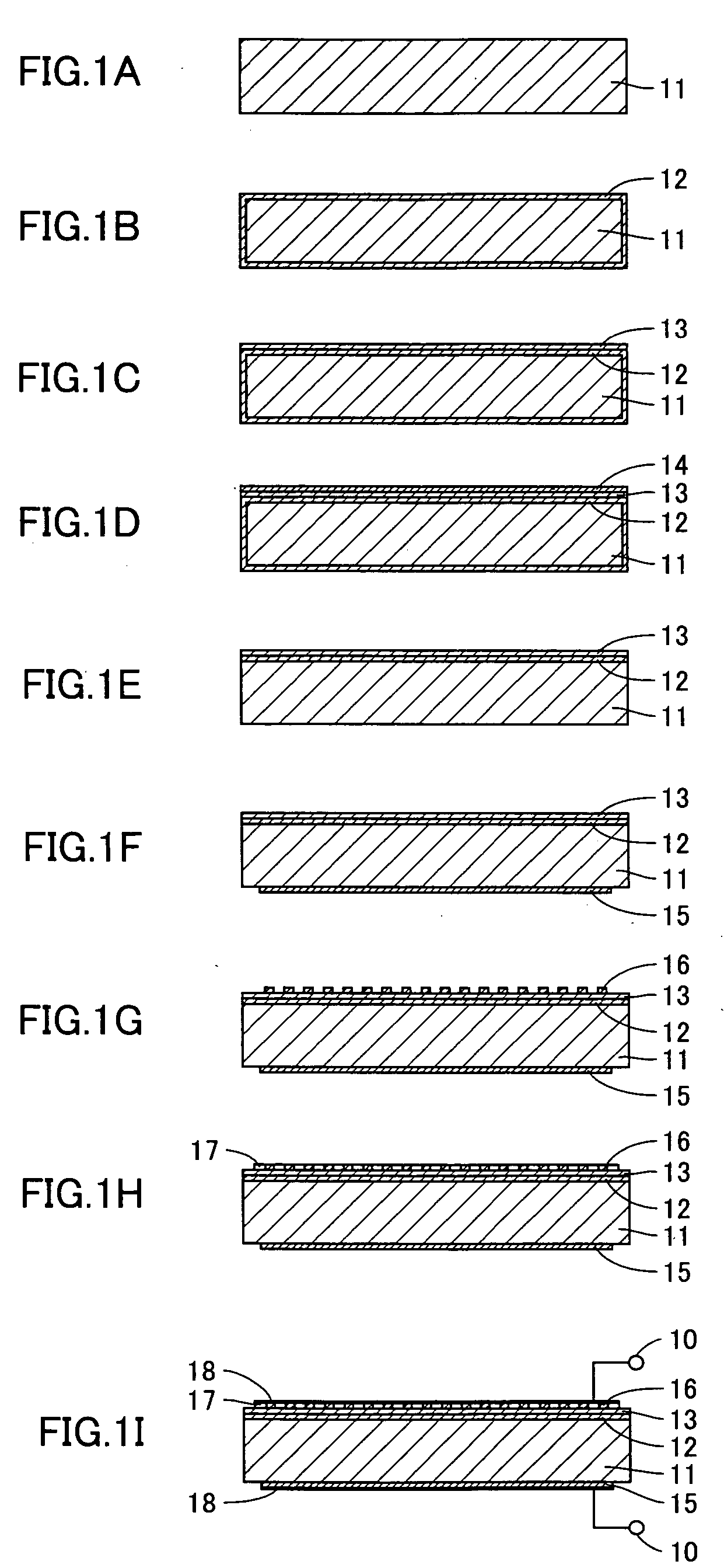
[0041] The solar cell according to the present invention was manufactured in the steps shown in FIGS. 1A to 1I. First, the surface of a p-type silicon substrate 11 was treated with a high-temperature sodium hydroxide aqueous solution, so as to remove a surface damage layer (FIG. 1A). Then, an n+ layer (high concentration n layer) 12 was formed on the entire surface of p-type silicon substrate 11 through vapor phase diffusion of POCl3, as shown in FIG. 1B. Thereafter, the surface of n+ layer 12 was washed with hydrofluoric acid, and an antireflection coating 13 composed of silicon nitride was formed on the light-receiving surface side with plasma CVD (Chemical Vapor Deposition), as shown in FIG. 1C. Then, as shown in FIG. 1D, a resist ink layer 14 was formed on antireflection coating 13 by printing. Thereafter, a junction was separated by chemical etching with fluoro-nitric acid, and resist ink layer 14 was removed by a solvent (FIG. 1E). After the resist ink layer was removed, a sil...


PUM


Abstract

A solar cell attaining high efficiency in photoelectric conversion is provided. A method of manufacturing a solar cell having a grid electrode and a main electrode for external output of electric power from the grid electrode includes the steps of forming a small-width grid electrode on a light-receiving surface of a substrate having a pn junction by sintering a metal paste material, and forming a bar-shaped main electrode electrically connected to the grid electrode.

Description

[0001] This nonprovisional application is based on Japanese Patent Application No. 2003-349359 filed with the Japan Patent Office on Oct. 8, 2003, the entire contents of which are hereby incorporated by reference. FIELD OF THE INVENTION [0002] The present invention relates to a solar cell having a pn junction, and more particularly to a solar cell attaining high efficiency in photoelectric conversion. DESCRIPTION OF THE BACKGROUND ART [0003] In recent days, a solar cell directly converting solar energy to electric energy has increasingly been expected to serve as a next-generation energy source in particular from a viewpoint of global environmental issues. Among various types of solar cells such as a solar cell using a compound semiconductor or an organic material, a solar cell using silicon crystal is mainly employed these days. [0004] In order to improve photoelectric conversion efficiency in a solar cell, an electrode structure in which an area for a light-receiving surface elect...

Claims


Application Information

Patent Timeline
IPC IPC(8): H01L31/00H01L31/04H01L31/0224H01L31/042H01L31/18
CPCH01L31/022425Y02E10/52H01L31/022433Y02E10/50H01L31/04H01L31/0224H01L31/18
Inventor ASAI, MASAHITO
Owner SHARP KK
Why Eureka
Try Eureka