Electromagnetically driven membrane mirror assembly

a membrane mirror and magnetoelectric technology, applied in the direction of optical elements, optical radiation measurement, instruments, etc., can solve the problems of affecting the accuracy, reliability, efficiency, and accuracy of free-space optical communication systems, and achieve the effect of avoiding deficiencies

Active Publication Date: 2005-09-08
EOS DEFENSE SYST USA INC
View PDF6 Cites 5 Cited by
  • Summary
  • Abstract
  • Description
  • Claims
  • Application Information

AI Technical Summary

Benefits of technology

[0011] In an adaptive optics system, a direct drive membrane mirror assembly avoids the deficiencies of acoustically driven membrane mirrors while achieving proper deformations for use in wavefront sensors. This is accomplished by driving the membrane mirror electromagnetically rather than with air pressure. For example, an electrical current is directed through the mirror, or a conductor attached to the mirror, in the presence of a magnetic field. This causes a generally uniform force on the mirror that tends to deflect the membrane mirror into a convex or concave position, depending on the orientation of the force.

Problems solved by technology

While the use of fiber optics has increased the capacity and efficiency of data transmission, there are many situations where the installation of new fiber is not the best solution.
However, in many of these potential applications, the free-space optical communications link suffers from optical aberrations.
For example, changes in atmospheric conditions can be a significant impediment to the accuracy, reliability, and efficiency of free-space optical communications systems.
Wind, heat waves, man-made pollutants, and other effects can create constantly changing aberrations.
This, in turn, can degrade the quality of the optical signal that is available at the receiver, resulting in degradation of the overall quality and efficiency of the communications channel.
However, such mirrors are difficult to manufacture in a small form factor and tend to be somewhat unstable over time.
Additionally, an acoustic driving mechanism cannot work in environments with little or no air, such as in space and high flying aircraft applications.
Acoustic systems also suffer from poor performance due to complicated resonance peaks at various frequencies.
Moreover, acoustic systems are highly sensitive to their environment, where changing temperatures and / or pressures during operation further complicates the performance characteristics of the wavefront sensor.
Although acoustic drivers tend to exert this uniform pressure, they suffer from the drawbacks outlined above.

Method used


Image

  • Electromagnetically driven membrane mirror assembly
  • Electromagnetically driven membrane mirror assembly
  • Electromagnetically driven membrane mirror assembly

Examples


Embodiment Construction

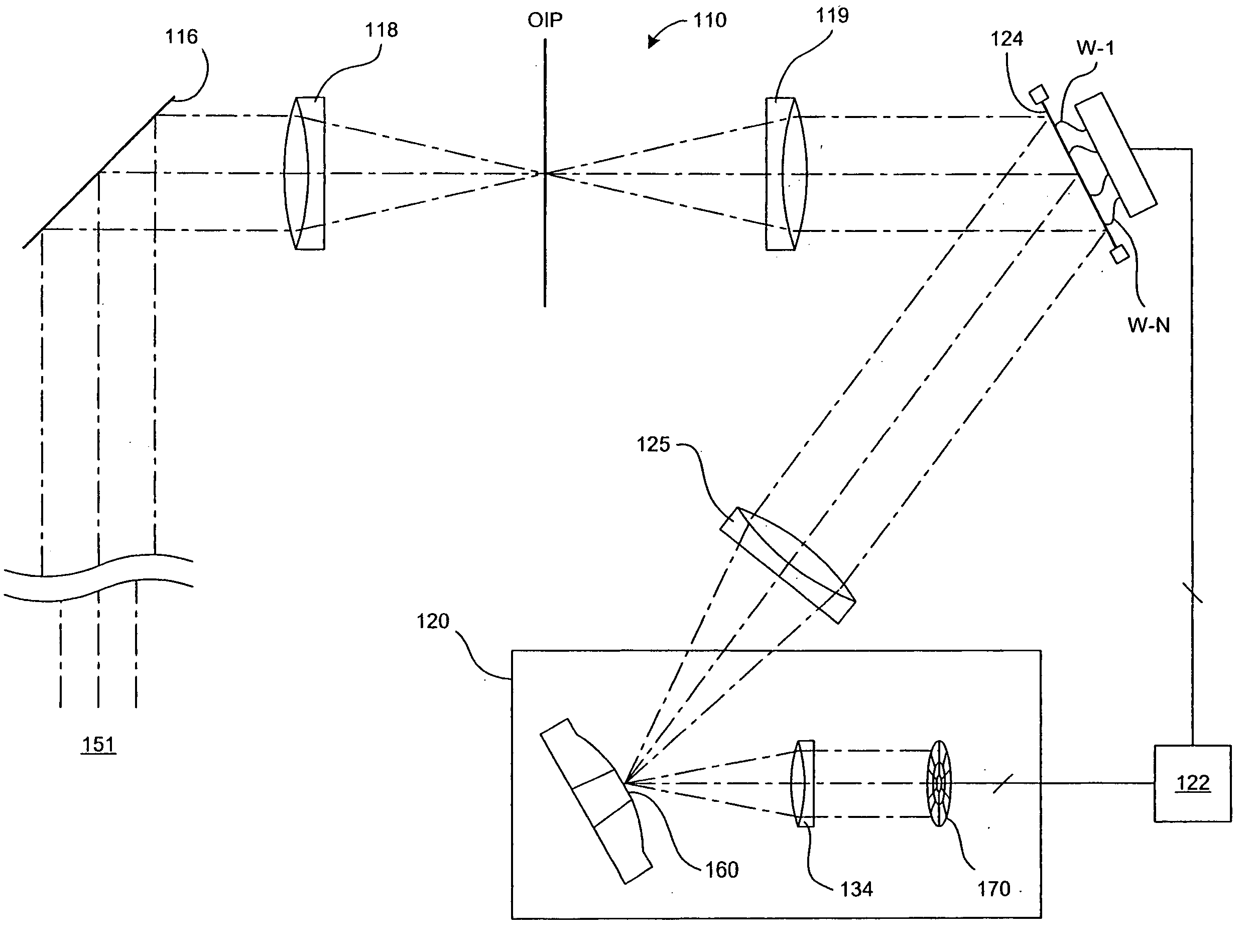
[0019] In one embodiment of the present invention, a direct drive membrane mirror is provided for use in a wavefront sensor of an adaptive optics system. FIG. 1 illustrates a specific implementation of an adaptive optics system that incorporates a wavefront sensor with a direct drive membrane mirror. This system includes a telescope 110 with an adaptive optics module. Light rays 151 from a remote light source enter the system via a tip-tilt mirror 116. The system may further include data transmitter and receiver portions, neither of which is shown in FIG. 1 for clarity.

[0020] In one application, the receiving telescope 110 is designed to be positioned vertically. The tip-tilt mirror 116 can be pivoted about two perpendicular axes, one on the vertical axis of the telescope like a turret and the other horizontal in the plane of the mirror. In this way, the tip-tilt mirror 116 enables tip and tilt adjustments of the incoming light. As an alternative, the telescope 110 may be rotatable...


PUM


Abstract

In an optics system, a flexible mirror is deformed with an electromagnetic force. In one embodiment, an electrical current is directed through the mirror, or a conductor attached to the mirror, in the presence of a magnetic field. In one application in an adaptive optics system, the membrane mirror is used in a wavefront sensor. Deformed to oscillate between convex and concave positions, the mirror is used to alternately defocus a received light signal for determining aberrations in the light signal. By detecting aberrations in the light signal, the adaptive optics system can correct for those aberrations.

Description

BACKGROUND [0001] 1. Field of the Invention [0002] This invention relates generally to membrane mirror assemblies as may be used in adaptive optics systems, and in particular to deforming a membrane mirror used in a wavefront sensor for detecting aberrations in light signals. [0003] 2. Background of the Invention [0004] There is an increasing interest in the use of free-space optical communications for various applications. For example, much of the current telecommunications infrastructure is based on the transmission of optical signals via optical fibers. While the use of fiber optics has increased the capacity and efficiency of data transmission, there are many situations where the installation of new fiber is not the best solution. As a result, there is interest in augmenting the telecommunications infrastructure by transmitting optical signals through the free-space of the atmosphere. [0005] Free-space optical communications links can also be used advantageously in applications ...

Claims


Application Information

Patent Timeline
Patent Type & Authority Applications(United States)
IPC IPC(8): G01J1/20
CPCG01J9/02G02B26/0825G01J2009/002
Inventor GRAVES, J. ELONNORTHCOTT, MALCOLM J.CHRISTOPHER SHELTON, J.DOUGLASS, JEFFREY W.
Owner EOS DEFENSE SYST USA INC
Why Eureka
Try Eureka