Fluorine compound, liquid repellent membrane using the same and product using the same

a technology of fluorine compound and liquid repellent membrane, which is applied in the direction of conductive pattern formation, other chemical processes, instruments, etc., can solve the problems of liquid repellent membrane having a function of ph, apparatus of more sophisticated structure, and cannot be realized, and achieves the effect of little selectivity

Inactive Publication Date: 2005-09-08
HITACHI LTD
View PDF3 Cites 32 Cited by
  • Summary
  • Abstract
  • Description
  • Claims
  • Application Information

AI Technical Summary

Benefits of technology

[0007] A technique of partly reducing repellency and depositing a liquid selectively on the portion of decreased repellency is applicable not only to electrical lines but also to display devices of thin film transistor (TFT) or organic electro luminescence (EL) element or the like, and color filter panels in which the above device is used. These techniques mainly use light, because of availability of relatively low-cost light source which allows high-precision fabrication of the order of microns. Use of electron beams will be also effective, because these beams allow fabrication of the order of nanometers. Moreover, the liquid repellent membrane is expected to have greatly expanded applicable areas, when it can work with a physical stimulation, e.g., heat, pH, pressure, electricity or electric charge. It is also possible to develop a surface which can be controlled for its wettability by two or more stimulation types, when the liquid repellent membrane once formed can be provided with an acceptor which accepts a physical stimulation.
[0008] When repellency is to be controlled with light, even the newly proposed techniques need a vacuum process as is the case with conventional techniques, because of necessity for light having a wavelength of 172 nm, which is in the vacuum ultraviolet region, for direct photolysis of a fluorine compound. Therefore, a vacuum process which involves a vacuum chamber and the like is needed, although a vacuum deposition process may be dispensed with. Consequently, there are demands for those methods which can perform patterning with light of longer wavelength, more specifically 250 nm or more, and hence need no vacuum chamber. The light sources fall into two general categories, lamp (e.g., mercury or xenon lamp) and laser. A lamp-aided apparatus needs a lens system to collect outputted light, and also a suitable mask when fine electrical lines or the like are to be formed by light. A laser-aided apparatus, on the other hand, needs no collection of light it emits, because it runs more straight, and a desired portion can be selectively irradiated with light by scanning the surface by the laser set on an xy plotter or the like. Therefore, a laser-aided apparatus is advantageous over a lamp-aided apparatus, because of simplified structure and reduced cost. However, a common semiconductor laser can only emit light in the visible region, e.g., light of 830, 780, 630 or 405 nm in wavelength. Another laser can emit light of shorter wavelength. However, such a laser needs an apparatus of more sophisticated structure, and is difficult to move for forming electrical lines. Consequently, there are demands for liquid repellent membranes whose wettability can be controlled by a semiconductor laser.
[0010] The inventors of the present invention have successfully synthesized, after having extensively studied to solve the above problems, a variety of species of fluorine compounds having, in their chemical structures, a site at which they can be bound to a metal or glass and another site at which they can be bound to a residue. It is found that the compound gives a membrane which exhibits water repellency with a contact angle of 100° or more, when bound to a metal or glass. It is also found that the liquid repellent membrane can be bound to some colorants, because the fluorine compound in the membrane has in itself a site at which it can be bound to another compound. The liquid repellent membrane to which a colorant is bound can have decreased liquid repellency at the portion irradiated with light of wavelength absorbable by the colorant.
[0011] The method for reducing liquid repellency of a liquid repellent membrane by the aid of light depends on a principle that a colorant bound to the membrane is irradiated with light to convert the light energy to heat, by which the member constituting the membrane is thermally decomposed to decrease the liquid repellency.
[0012] It is observed that a membrane incorporated with a crown ether or the like in place of colorant has a decreased contact angle, when immersed in an aqueous solution of a metal which can be held in the membrane. It is also observed that a membrane having amino group serving as the binding site has a decreased contact angle, when immersed in an aqueous acidic solution, e.g., hydrochloric acid, conceivably because amino group is transformed into an ammonium salt structure to be more hydrophilic to generally decrease liquid repellency of the liquid repellent membrane. As discussed above, the inventors of the present invention have found that liquid repellent membrane can have selectively controlled liquid repellency depending on a substance with which it is treated, achieving the present invention. The present invention includes the following aspects.
[0029] The 16th aspect is a method for producing an electrical board by forming a liquid repellent membrane on a board, irradiating part of the liquid repellent membrane with light to decrease liquid repellency of that part, and spreading a solution in which an electrical line material is dissolved or dispersed on the part of decreased repellency and drying the solution, wherein a fluorine compound represented by one of the following structures is used for the liquid repellent membrane: wherein, X is a structure represented by one of the following formulae, and R is an alkyl group of 1 to 4 carbon atoms:

Problems solved by technology

However, these materials have not been disclosed, and a liquid repellent membrane having a function of, e.g., changing in water repellency with some ion species or pH, cannot be realized.
However, such a laser needs an apparatus of more sophisticated structure, and is difficult to move for forming electrical lines.

Method used


Image

  • Fluorine compound, liquid repellent membrane using the same and product using the same
  • Fluorine compound, liquid repellent membrane using the same and product using the same
  • Fluorine compound, liquid repellent membrane using the same and product using the same

Examples


synthesis example 1

[0099] SYNTHESIS EXAMPLE 1 produced a perfluoropolyether (Compound 1, represented by the following formula) with epoxy group as X.

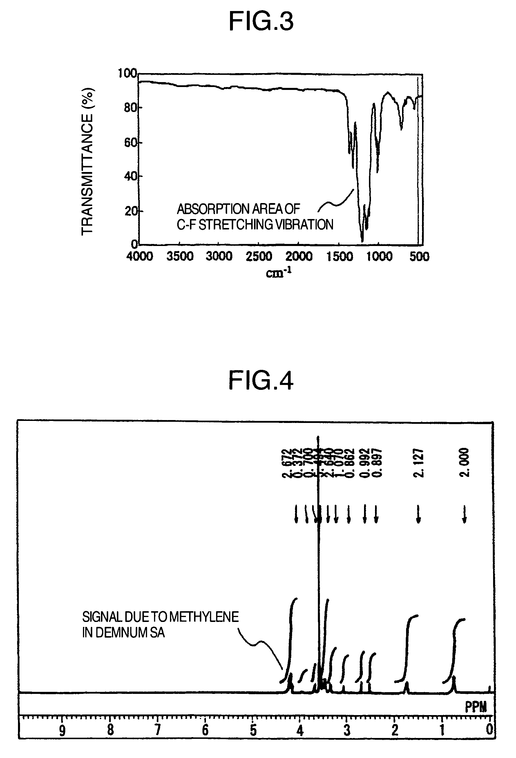
[0100] First, 10 parts by weight of DEMNUM SA (Daikin Kogyo, average molecular weight: 4000) and 0.1 parts by weight of DEMNUM SH (Daikin Kogyo, average molecular weight: 4000) were dissolved in 50 parts by weight of HFE-7200 (3M), to which 2 parts by weight of 3-glycidoxypropyltrimethoxysilane was added, and the mixture was stirred at 80° C. for 10 minutes. HFE-7200 was evaporated essentially totally during the stirring period. Next, the mixture was stirred at 100° C. for 4 hours, and cooled to normal temperature. The resulting residue was incorporated with 200 parts by weight of PF-5060 (3M) and 200 parts by weight of dichloromethane, and stirred. The mixture was separated into two phases in a couple of hours after it was allowed to stand. The lower phase was separated 24 hours after it was allowed to stand, and treated to remove PF-5060 as a solvent ...

synthesis example 2

[0104] SYNTHESIS EXAMPLE 2 produced a perfluoropolyether (Compound 2, represented by the following formula) with epoxy group as X.

[0105] First, 50 parts by weight of KRYTOX 157FS-L (Du Pont, average molecular weight: 2500) was dissolved in 100 parts by weight of HFE-5080 (3M), to which 2 parts by weight of lithium aluminum hydride was added, and the mixture was stirred at 80° C. for 48 hours with stirring. Then, ice water was added to the reaction solution, to separate it into two phases. The lower phase was separated, washed with 1% hydrochloric acid, and washed with water until it became neutral. It was then passed through a filter paper to remove water, and treated to remove PF-5080 by an evaporator, to produce 45 parts by weight of Compound 2′, which was KRYTOX 157FS-L with its terminal converted into CH2OH.

[0106] Then, 10 parts by weight of Compound 2′ was dissolved in 0.1 parts by weight of KRYTOX 157FS-L and 50 parts by weight of HFE-7200 (3M), to which 4 parts by weight o...

synthesis example 3

[0110] SYNTHESIS EXAMPLE 3 produced a perfluoropolyether (Compound 3, represented by the following formula) with epoxy group as X.

[0111] First, 10 parts by weight of FOMBRIN Z-DOL (Ausimont, average molecular weight: 4000) and 0.1 parts by weight of FOMBRIN Z-DIAC (Ausimont, average molecular weight: 4000) were dissolved in 50 parts by weight of HFE-7200 (3M), to which 4 parts by weight of 3-glycidoxypropyltrimethoxysilane was added, and the mixture was stirred at 80° C. for 10 minutes. HFE-7200 was evaporated essentially totally during the stirring period. Next, the mixture was stirred at 100° C. for 4 hours, and cooled to normal temperature. The resulting residue was incorporated with 1000 parts by weight of PF-5060 (3M) and 1000 parts by weight of dichloromethane, and stirred. The mixture was separated into two phases in a couple of hours after it was allowed to stand. The lower phase was separated 24 hours after it was allowed to stand, and treated to remove PF-5060 as a solve...


PUM

PropertyMeasurementUnit
wavelengthaaaaaaaaaa

Abstract

The present invention provides a liquid repellent membrane whose liquid repellency can be controlled by a varying physical stimulation; a novel fluorine compound which can be formed into the liquid repellent membrane; an electrical board, display device and color filter for display devices which are formed using the liquid repellent membrane by a method involving irradiation of visible light, which may be combined with a heating step, but needing no vacuum or ultraviolet ray irradiation process; methods for producing an electrical board, display device and color filter for display devices; and a pH sensor and ion sensor working on measurement of changed liquid repellency. The fluorine compound having liquid repellency is provided with a site at which it can be bound to a functional group, e.g., compound having a pigment unit.

Description

FIELD OF THE INVENTION [0001] The present invention relates to a fluorine compound, liquid repellent membrane using the same compound, and various products using the same membrane. BACKGROUND OF THE INVENTION [0002] Recently, new techniques have been proposed to produce boards, wherein a membrane having liquid repellency (hereinafter referred to as “liquid repellent membrane”) formed on a board is partly treated to lose the repellency and then coated with a liquid in which fine particles are dissolved or dispersed on the treated part. These boards are expected to go into various devices, e.g., display for TV sets, electrical board for electronic devices (e.g., radios and personal computers), color filter panel for liquid crystal displays, and board for organic electroluminescent (hereinafter referred to as “organic EL”) devices for EL displays. [0003] Some of these techniques are disclosed by, e.g., Patent Document 1. [0004] (Patent Document 1): JP-A 2000-282240 BRIEF SUMMARY OF THE...

Claims


Application Information

Patent Timeline
Patent Type & Authority Applications(United States)
IPC IPC(8): C07F7/10C07F7/18C09K3/18H05B33/10G02B5/20H01L29/08H01L35/24H01L51/05H01L51/50H05B33/14H05K3/12
CPCC07F7/1836G02B5/201H05K2203/1173H05K3/1208H05K3/1241H01L51/0529C07F7/1804H10K10/474
Inventor SASAKI, HIROSHITOMIOKA, YASUSHI
Owner HITACHI LTD
Why Eureka
Try Eureka