
Electrical connection materials and electrical connection methods

a technology of electrical connection and material, applied in the direction of optics, instruments, and semiconductor/solid-state device details, etc., can solve the problems of inability to obtain conductivity between the connected electrodes, the inability to maintain the insulated relationship between the adjacent electrodes, and the number of contact points

Inactive Publication Date: 2005-09-08
SONY CORP
View PDF2 Cites 2 Cited by
  • Summary
  • Abstract
  • Description
  • Claims
  • Application Information

AI Technical Summary

Benefits of technology

[0024] The present invention was developed considering the above points, and an object of the present invention is to provide electrical connection materials and electrical connection methods by which an electrical connection via conductive particles can be reliably performed regardless of a little unevenness in objects.
[0041] The diameter of the second filler particles contained in the second film-like adhesive layer is set to a value larger than the diameter of the first filler particles contained in the first film-like adhesive layer. Since the diameter of the second filler particles is set to a value larger than the diameter of the first filler particles, it is possible that the viscosity of the second film-like adhesive layer containing the second filler particles with a larger diameter is lower and the viscosity of the first film-like adhesive layer containing the first filler particles is higher.
[0044] The content of the second filler contained in the second film-like adhesive layer is set to a value smaller than the content of the first filler contained in the first film-like adhesive layer. Since the content of the second filler is set to a value smaller than the content of the first filler, it is possible that the viscosity of the second film-like adhesive layer containing the second filler with a small content is lower and the viscosity of the first film-like adhesive layer containing the first filler is higher.
[0046] In claim 8, by selecting a material for the first filler and the second filler, which can reduce the coefficient of water absorption and the coefficient of linear expansion of an adhesive layer, for example, the reliability of the electrical connection between a wiring pattern on a circuit substrate and a protrusion electrode of an electrical component can be improved.
[0047] By reducing the water absorption coefficient of an adhesive layer, occurrence of package crack due to moisture absorption of the adhesive layer can be restrained in a production process accompanied by a reflow furnace.
[0048] By reducing the linear expansion coefficient, stress developed from the difference of the linear expansion coefficients of the first object and the second object due to thermal stress can be mitigated in the adhesive layer, and the connection reliability for thermal stress can be improved.

Problems solved by technology

However, in this method, when the diameter of the conductive particle is made small, due to a remarkable increase of the surface area of the conductive particle, the conductive particles cause secondary agglomeration to couple with each other so that the insulated relationship between the adjacent electrodes cannot be maintained.
Further, when the content of the conductive particles is reduced, since the number of the conductive particles on the electrodes to be connected is reduced, the number of contact points becomes insufficient, and conductivity between the connected electrodes cannot be obtained.
Thus, it is difficult to make the connection member cope with a fine pitch while maintaining a long period of electrical connection reliability.
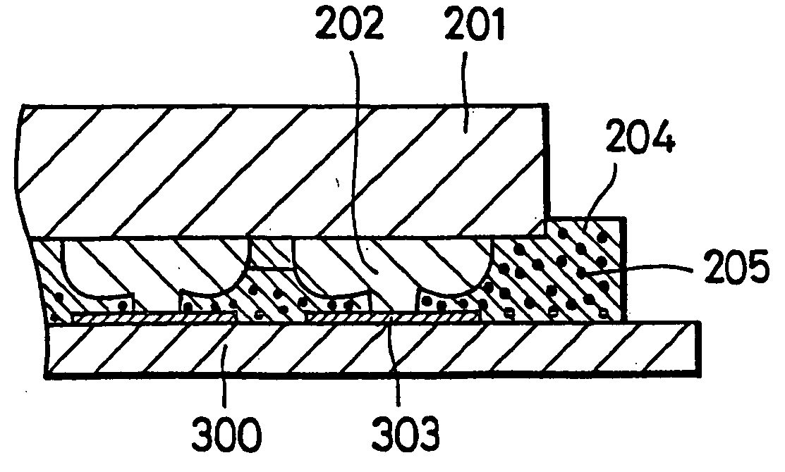
However, the conductive particles 205 do not participate in all connections, and thus electrical connections cannot be obtained.
Or since it is necessary to obtain components with strict specifications, the cost increases.

Method used


Image

  • Electrical connection materials and electrical connection methods
  • Electrical connection materials and electrical connection methods
  • Electrical connection materials and electrical connection methods

Examples


Embodiment Construction

[0074] Hereafter, one preferred embodiment of the present invention is explained in detail based on attached drawings.

[0075] Since an embodiment described below is a preferred specific example of the present invention, various limitations which are technically preferred are added, however, the scope of the present invention is not limited to the features as far as there is no description that the present invention is limited specifically in the following explanation.

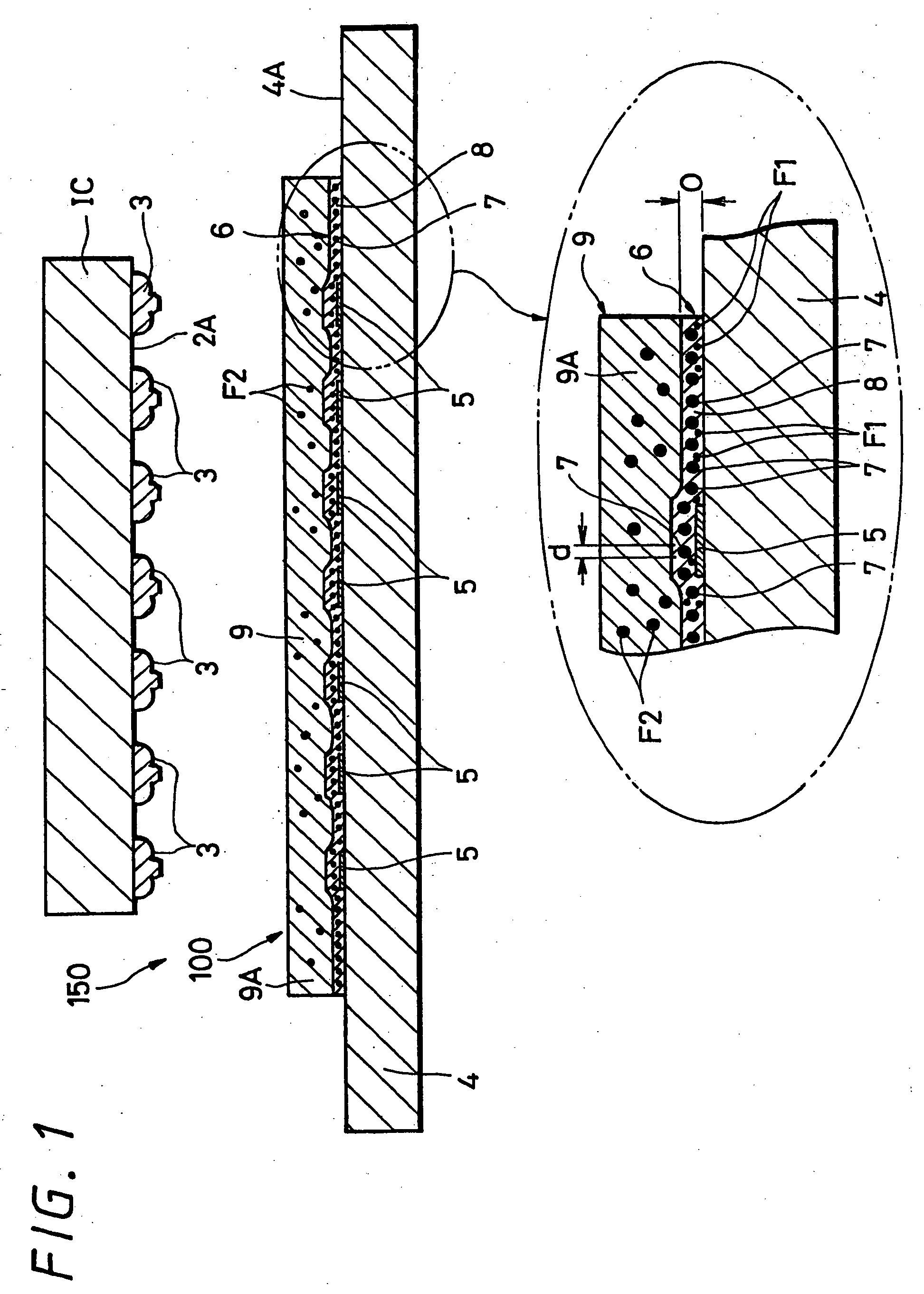
[0076]FIG. 1 shows one example of an electrical device 150 electrically connected according to a preferred embodiment of an electrical connection material 100 of the present invention. This electrical device 150 is provided with a printed wiring board 4 and an IC (integrated circuit) 2 as an example of an electrical component.

[0077] A wiring pattern 5 in a shape of a predetermined pattern is formed on one face 4A of the printed wiring board 4. This wiring pattern 5 is an electrical wiring pattern formed, for example, ...


PUM


Abstract

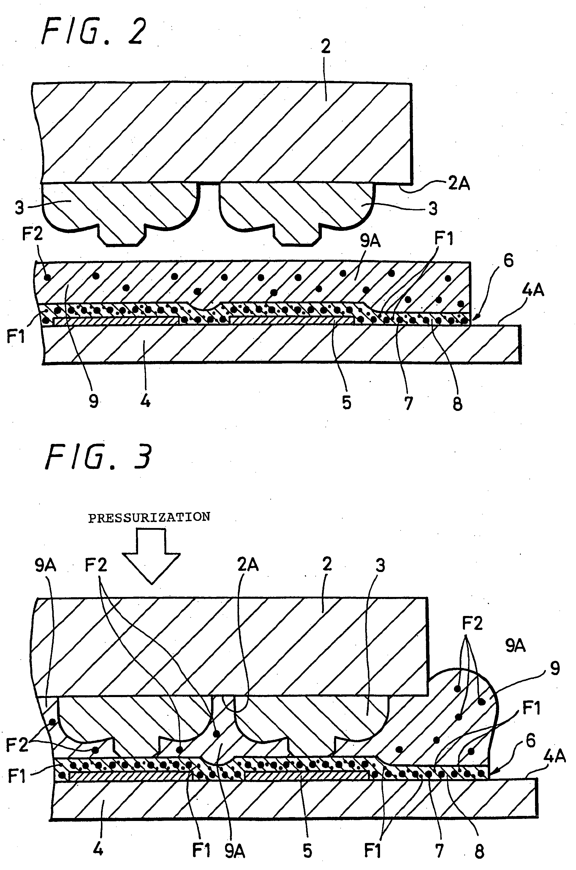
The present invention is to provide an electrical connection material through which an electrical connection via conductive particles can be performed reliably regardless of a little unevenness of an object. The electrical connection material is an electrical connection material 100 for electrically connecting an electrical connection portion of a first object 4 and an electrical connection portion of a second object 2. The electrical connection material 100 comprises a first film-like adhesive layer 6 which is a film-like adhesive layer arranged on the first object 4 and is composed of a plurality of conductive particles 7, a first binder 8 containing the conductive particles 7, and a first filler F1 and a second film-like adhesive layer 9 which is arranged on the first film-like adhesive layer 6 and is composed of a second binder 9A whose viscosity is lower than that of the first binder 8 and a second filler F2.

Description

TECHNICAL FIELD [0001] The present invention relates to electrical connection materials and electrical connection methods for electrically connecting a first object electrical connection portion and a second object electrical connection portion. BACKGROUND ART [0002] As an example, portable type information terminals, specifically, electronic equipment such as, for example, portable telephones, are required to be compact and thin, and thus a high density, high resolution circuit employed in such electronic equipment has been developed. [0003] For the connection between an electronic component and a fine electrode, since conventional solder or a rubber connector or the like does not deal with such connection well, an adhesive agent or a film-like material (hereafter, referred to as a connection member) which is anisotropic, excellent in a fine pitch and has conductivity has been employed frequently. [0004] This connection member is comprised of an adhesive agent containing a predeter...

Claims


Application Information

Patent Timeline
IPC IPC(8): H01L21/56H01L21/60H01R4/04H05K3/32
CPCH01L21/563H01L24/31H01L2924/0665H01L2924/014H01L2924/01033H01L2924/01006H01L2924/00013H01L2224/2919H01L2224/73204H01L2224/32225H01L24/29H05K2203/1189H05K2201/10674H05K2201/0209H05K3/323H01R4/04H01L2924/14H01L2924/0781H01L2924/01079H01L2924/01078H01L2924/0105H01L2924/01049H01L2924/01029H01L2924/01027H01L2924/01013H01L2924/01005H01L2224/838H01L24/83H01L2224/1134H01L2224/13144H01L2224/16225H01L2224/73203H01L2224/83192H01L2224/83194H01L2924/00014H01L2224/13099H01L2924/00H01L2924/3512H01L2224/45144H01L2924/351
Inventor HONDA, NORIYUKIHANAI, NOBUHIRONAKADA, MASAKAZU
Owner SONY CORP
Learn More