Optical device, method of producing the same, optical pickup, and optical information processing device

a technology of optical information processing and optical picks, which is applied in the direction of instruments, polarising elements, other domestic objects, etc., can solve the problems of many processing steps, large space occupied in the arrangement, and limited size of the optical picks, so as to reduce the size and cost, and achieve high compatibility

Inactive Publication Date: 2005-09-08
RICOH KK
View PDF20 Cites 45 Cited by
  • Summary
  • Abstract
  • Description
  • Claims
  • Application Information

AI Technical Summary

Benefits of technology

[0042] According to the present invention, in an optical device having polarized light diffraction functions realized by a sub-wavelength grating, and an optical pickup having such an optical device, a phase difference does not occur between a region where the sub-wavelength grating is formed and a region where the sub-wavelength grating is not formed, and due to this, undesirable wave front degradation does not happen. Therefore, it is possible to obtain an optical device having functions of aperture limitation for polarized light selection, aberration correction, phase shifter, or functions of a wave plate, and by incorporating these optical devices, it is possible to obtain an optical pickup of high compatibility, a multi-beam optical pickup, and a super-high resolution optical pickup; and an optical information processing device using these optical pickups.
[0043] In addition, according to the present invention, it is possible to obtain an optical device which can be fabricated without a surface coating process, which enables functions of multiple parts to be shared, and enables reduction of the size and the cost.

Problems solved by technology

On the other hand, the size of the optical pick is limited, and cannot be made larger than this limit.
As for the optical parts, such as a prism of a polarized beam splitter, there exist problems of many processing steps and a large space occupied in the arrangement.
Due to this structure, complicated processing steps are required compared to plate elements.
In addition, an optical part having such a cubic structure occupies considerable space inside the optical pickup.
However, when using the quartz crystal, because it is necessary to process the optical crystal with the primary axis of the crystal being in a specified direction, and direction precision is also required when assembling the optical pickup, there is a negative effect on cost reduction.
When using the liquid crystal, the liquid crystal has to be sealed by using two glass substrates, and this also causes increased cost.
However, when the sub-wavelength grating is formed only in a limited region, a light path length difference, and in turn, a phase difference is generated between the region where the sub-wavelength grating is formed and the region where the sub-wavelength grating is not formed; due to this, a wave front aberration is generated, and this degrades the light condensing properties of the object lens.

Method used


Image

  • Optical device, method of producing the same, optical pickup, and optical information processing device
  • Optical device, method of producing the same, optical pickup, and optical information processing device
  • Optical device, method of producing the same, optical pickup, and optical information processing device

Examples


first embodiment

[0080] First Embodiment

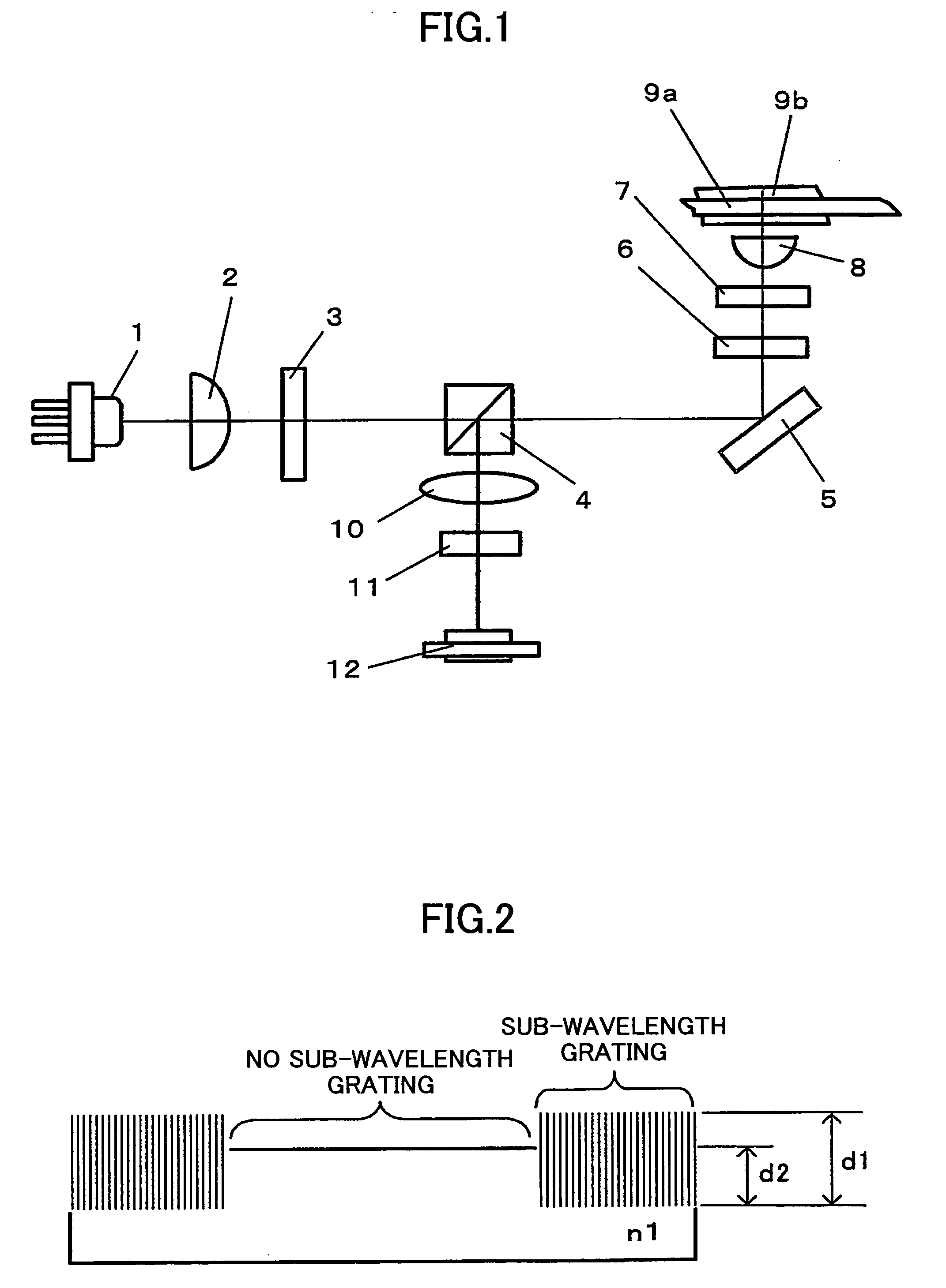
[0081]FIG. 1 is a schematic view illustrating an optical pickup according to a first embodiment of the present invention.

[0082] The optical pickup illustrated in FIG. 1 is used for recording, reproducing or erasing data in an optical recording medium A and an optical recording medium B which use light of different wavelengths, substrates of different thicknesses, and have different numerical apertures. Specifically, the optical recording medium A is a blue light optical recording medium which uses light of a wavelength equaling 405 nm, has a numerical aperture NA 0.85, and has a substrate of thickness equaling 0.1 mm on the incidence side. The optical recording medium B is a blue light optical recording medium, which uses light of a wavelength equaling 405 nm, has a numerical aperture NA 0.65, and has a substrate of thickness equaling 0.6 mm on the incidence side.

[0083] A principal portion of the optical pickup illustrated in FIG. 1 includes a semiconductor ...

second embodiment

[0160] Second Embodiment

[0161] In the present embodiment, an optical pickup is able to record, reproduce or erase data in a blue-light optical recording medium A, which uses light of wavelength 405 nm, having a numerical aperture NA 0.85, and having a substrate thickness of 0.1 mm on the incidence side; and is able to record, reproduce or erase data in a blue-light optical recording medium B, which uses light of wavelength 405 nm, has a numerical aperture NA 0.65, and a substrate thickness of 0.6 mm on the incidence side. Furthermore, the optical pickup is able to record, reproduce or erase data in a DVD optical recording medium C, which uses light of wavelength 660 nm, having a numerical aperture NA 0.65, and having a substrate thickness of 0.6 mm on the incidence side; and a CD optical recording medium D, which uses light of wavelength 785 nm, has a numerical aperture NA 0.50, and a substrate thickness of 1.2 mm on the incidence side.

[0162]FIG. 11 is a schematic view illustrating...

third embodiment

[0194] Third Embodiment

[0195]FIG. 14 is a schematic view illustrating an optical pickup according to a third embodiment of the present invention.

[0196] The optical pickup illustrated in FIG. 14 is a multi-beam optical pickup having a light source array including two channels. Below, a description is made of a sub-wavelength grating functioning as a wave plate, with a polarization direction switching element in the multi-beam optical pickup as an example.

[0197] A principal portion of the multi-beam optical pickup illustrated in FIG. 14 includes light source unit 31, a collimator lens 2, a two-beam light path combination element 33, a half mirror 4, a deflection prism 5, an object lens 8, a detection lens 10, a light beam deflection element 11′, and a light receiving element 12.

[0198] With the multi-beam optical pickup, it is possible to increase operating speed by recording or reproducing two tracks at the same time. Alternatively, with one light beam to perform recording, and wit...


PUM

PropertyMeasurementUnit
thicknessaaaaaaaaaa
thicknessaaaaaaaaaa
thicknessaaaaaaaaaa

Abstract

An optical device having a sub-wavelength grating formed in a specified region is disclosed that is able to prevent wave front degradation accompanying a phase difference of a polarized light beam passing through the optical device. The optical device includes a circular-belt-like region where the sub-wavelength diffraction grating is formed, and a center portion where the sub-wavelength diffraction grating is not formed. A vertically polarized light beam used for operations on a blue-light optical recording medium A has a phase difference in the sub-wavelength diffraction grating to be an integral multiple of 2π and hence is transmitted through the sub-wavelength diffraction grating. A horizontally polarized light beam used for operations on a blue-light optical recording medium is diffracted by the sub-wavelength diffraction grating. The light path length L1 of the light beam passing through the circular-belt-like region is the same as that of the light beam passing through the center portion without the sub-wavelength grating.

Description

BACKGROUND OF THE INVENTION [0001] 1. Field of the Invention [0002] The present invention relates to an optical device used in an optical pickup for recording, reproducing, or erasing information in an optical recording medium, a method of producing the optical device, an optical product, an optical pickup and an optical information processing device. [0003] 2. Description of the Related Art [0004] In the related art, an optical pickup in the present technical field is constituted by assembling many optical parts such as lenses, prisms, wave plates, polarized-light optical devices, and so on. In recent years and continuing, it is required that an optical pickup be able to support not only conventional CDs or DVDs, but also new optical recording media conforming with plural new and old standards, such as large capacity blue-light optical recording media. To meet this requirement, the number of the optical parts may further increase. On the other hand, the size of the optical pick is ...

Claims


Application Information

Patent Timeline
Patent Type & Authority Applications(United States)
IPC IPC(8): G02B6/34G02B5/18G11B7/123G11B7/1353G11B7/1381G11B7/139G11B7/22
CPCG02B5/1809G02B5/1847G11B7/1205G02B27/4238G11B7/139G11B2007/0006G11B7/1353G11B7/123G11B7/1381
Inventor HIRAI, HIDEAKIUMEKI, KAZUHIRO
Owner RICOH KK
Why Eureka
Try Eureka