Method of and system for signal separation during multivariate physiological monitoring

Inactive Publication Date: 2005-09-08
PEARLMAN JUSTIN D
View PDF21 Cites 50 Cited by
  • Summary
  • Abstract
  • Description
  • Claims
  • Application Information

AI Technical Summary

Benefits of technology

[0031] The problems of performing diagnostic testing on the heart are solved by the present invention of a new electrode-based monitoring system that uses multiple electrodes to create a multivariate characterization of the status of the heart (or other organ). An example of multivariate characterization is the description of a person in terms of height, weight, sex, eye color, interests, culture, education, and so on. The present invention collects multivariate data from contacts distributed on the body, and derives from the multivariate data a synthetic or composite sig

Problems solved by technology

The heart is not that simple, so the model introduces error well described in the literature.
The vector model is not as powerful at separating unwanted signals as is the multivariate method of this invention, it does not provide ST segment monitoring, and it requires a more difficult set up to be done properly.
There has historically been an assumption that finding the R-wave is the best approach to synchronization of imaging systems, however, the real issue for imaging is to find a time when the heart is filled to a matching volume and position so that data from multiple such times can be combined to form a coherent and consistent image.
For example, infarctions on the posterior or right aspects of the heart may be missed in a 12-lead ECG, and an enlarged or unusually positioned heart may not be adequately assessed with the standard 12-lead system.
In particular, myocardial infarcti

Method used


Image

  • Method of and system for signal separation during multivariate physiological monitoring
  • Method of and system for signal separation during multivariate physiological monitoring
  • Method of and system for signal separation during multivariate physiological monitoring

Examples


Example

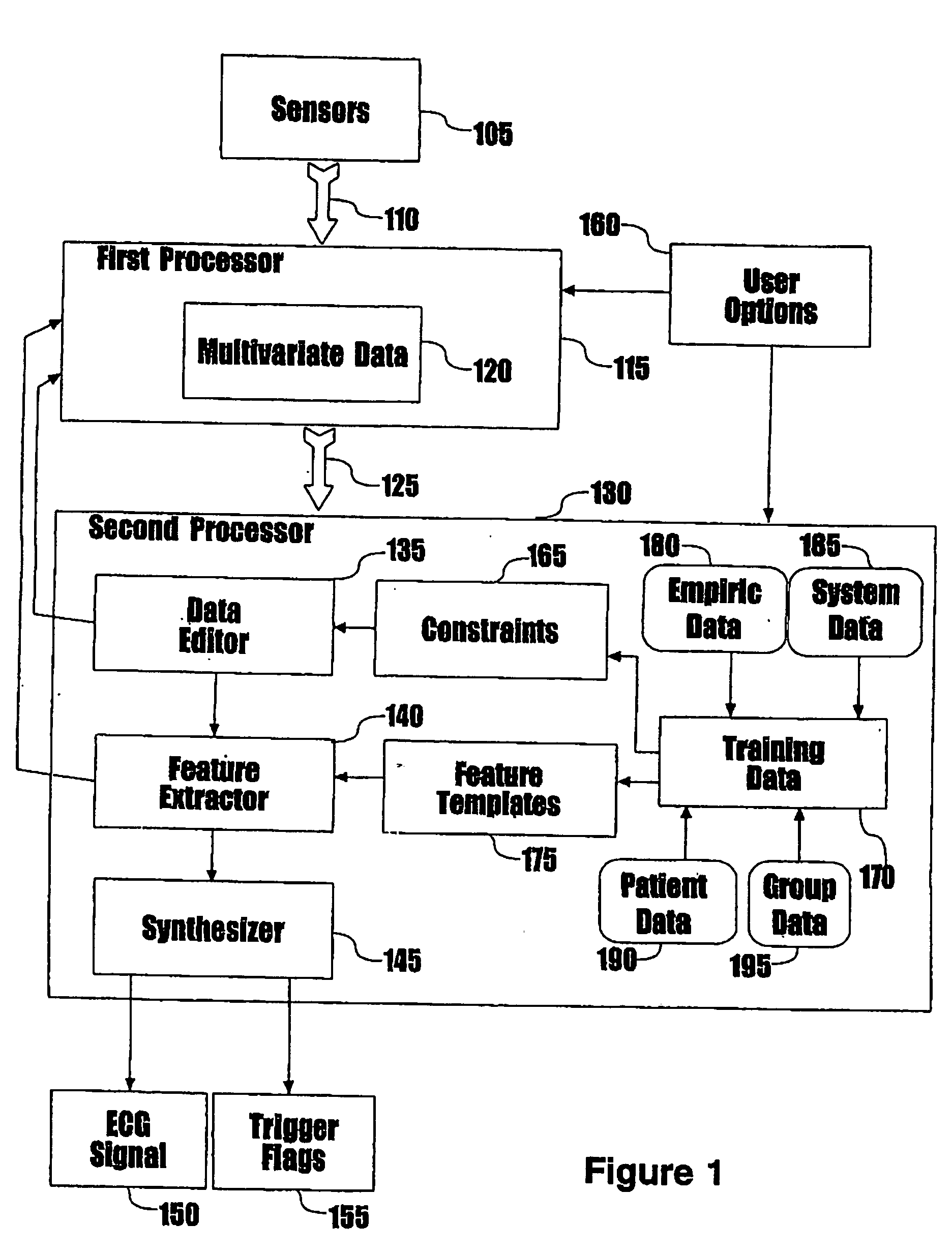
[0051] A preferred embodiment of the present invention incorporates therein a monitoring system that uses multiple electrodes to create a multivariate characterization of the status of the heart. During a training phase, the system utilizes template signals (the expression “training data” is used interchangeably) to compute values for a separability operator S that may be applied in real-time to subsequent observed data to separate distinct, superimposed signal sources from a desired physiologic signal.

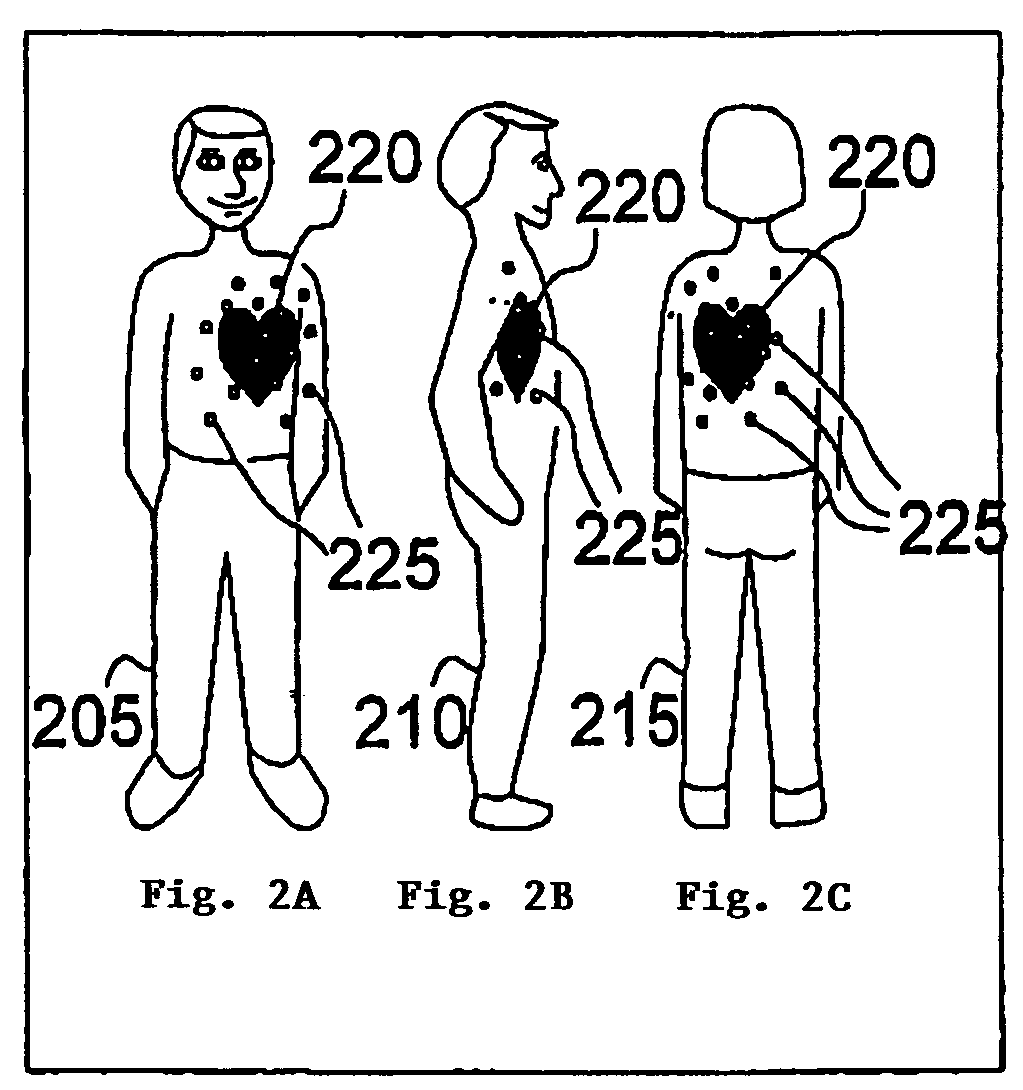
[0052] The template signals are used in the training phase to calibrate the system to separate mixed signals from a specific subject. Subjects differ in various ways, including height, distribution of muscle mass, flow in great vessels, and orientation of the electrical activation of the heart in relation to the other signal sources. The use of template signals takes less than one second, and can be repeated if desired to monitor for drift if conditions change radically (e.g., marked...


PUM


Abstract

Multiple electrode contacts make electrical connections to the anterior and/or posterior chest for multivariate characterization of the electrical activation of the heart. A central processing unit derives synthetic composite electrographic signals as well as flag signals for specific purposes. A preferred embodiment uses this system to trigger or gate magnetic resonance imaging, eliminating or reducing problems from small or inverted R-waves, lead detachment, noise, flow signal, gradient changes, and rhythm changes, more reliably flagging the onset of electrical activation of the ventricles. Additional derived data are ST-segment shifts, filling times, and respiratory cycle. Filling times may be used for greatly improved imaging in the presence of rhythm disturbances, such as atrial fibrillation. Respiratory cycle may be used as a respiratory trigger to control for the effects of breathing on the heart position and image quality.

Description

CROSS-REFERENCE TO RELATED APPLICATIONS [0001] This application is a continuation-in-part of pending U.S. Utility Application Ser. No. 09 / 773,167, filed Jan. 31, 2001, which in turn claims priority of U.S. Provisional Application Ser. No. 60 / 179,192 filed Jan. 31, 2000, both of which are entitled “Multivariate Cardiac Monitor” and are incorporated herein by reference in their entirety.FIELD OF THE INVENTION [0002] This invention relates generally to medical diagnostic testing and in particular, to a multivariate sensor system and methods of separating superimposed signals from useful physiologic signals such as, for example, magnetohydrodynamic signals from electrocardiographic signals or anterior wall signals from posterior wall signals. BACKGROUND OF THE INVENTION [0003] Electrocardiographic (ECG) measuring systems generally apply 3 electrodes (to the chest or 10 electrodes (4 limbs and 6 specific points on the chest) to the skin, and, through a differential operational amplifier ...

Claims


Application Information

Patent Timeline
IPC IPC(8): A61B5/0452
CPCA61B5/04525A61B5/7285A61B5/7239A61B5/04028A61B5/055A61B5/7267A61B5/327A61B5/35G16H50/70
Inventor PEARLMAN, JUSTIN D.
Owner PEARLMAN JUSTIN D
Why Eureka
Try Eureka