Exhaust gas purification system of internal combustion engine

Active Publication Date: 2005-09-15
DENSO CORP
View PDF12 Cites 46 Cited by
  • Summary
  • Abstract
  • Description
  • Claims
  • Application Information

AI Technical Summary

Benefits of technology

[0015] The deposition quantity of the exhaust particulate matters deposited in the particulate filter varies because the combustion of the deposited exhaust particulate matters varies inside the particulate filter. The exhaust gas purification system calculates the deposition bias based on the combustion distribution and compares the deposition bias with the reference value. Thus, the exhaust gas purification system determines whether the deposition variation in the particulate filter is large or not. If the deposition bias exceeds the reference value, the compulsory regeneration is performed to eliminate the deposited exhaust particulate matters substantially completely. Thus, the deposition quantity can be prevented from increasing excessively in a portion of the particulate filter. As a result, the occurrence of the partial rapid combustion in the particulate filter can be effectively prevented.
[0016] According to yet another aspect of the present invention, the exhaust gas purification system includes quantity calculating means for calculating a deposition quantity of the exhaust particulate matters deposited in a maximum deposition portion of the particulate filter based on the operating states of the engine including the combustion distribution in the particulate filter. The controlling means completes the compulsory regeneration to eliminate the deposited exhaust particulate mat

Problems solved by technology

If a quantity of the collected and deposited particulate matters (a deposition quantity) increases excessively, flow resistance in the particulate filter increases and a back pressure of the engine increases.
As a result, an output of the engine will be deteriorated.
If the compulsory regeneration is performed frequently, a fuel cost will increase.
If a time interval to the next generation is too long, the quantity of the deposited exhaust particulate matters will increase exces

Method used


Image

  • Exhaust gas purification system of internal combustion engine
  • Exhaust gas purification system of internal combustion engine
  • Exhaust gas purification system of internal combustion engine

Examples


Example

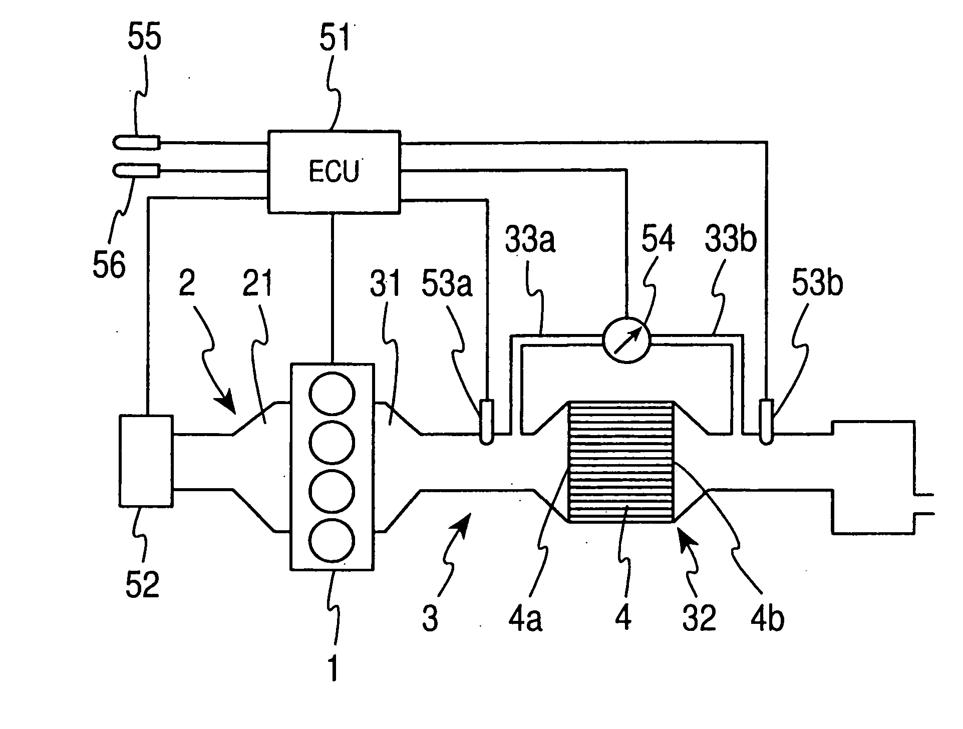
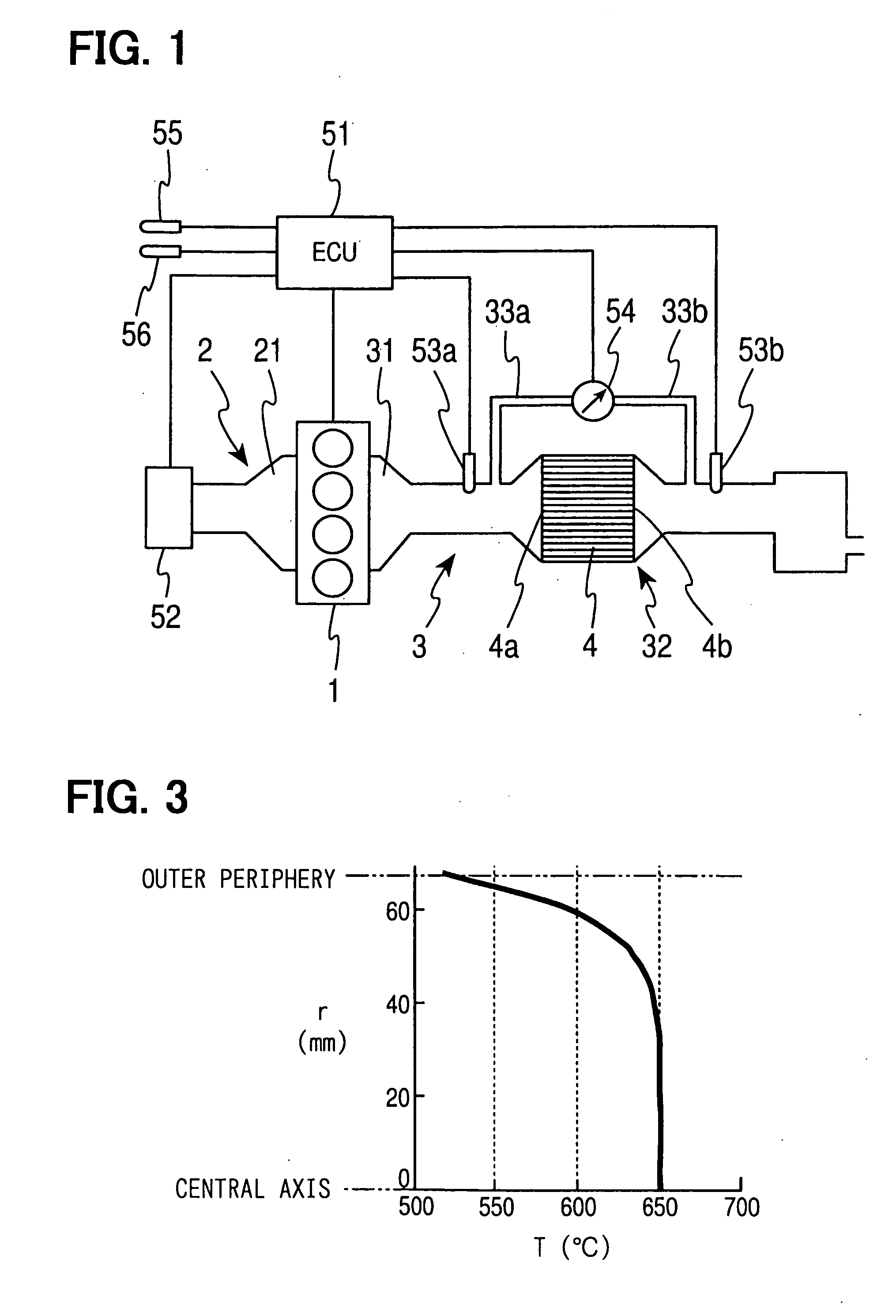
[0030] Referring to FIG. 1, a diesel engine according to a first embodiment of the present invention is illustrated.

[0031] An engine main body 1 of the diesel engine shown in FIG. 1 is equipped with four cylinders. The engine main body 1 is connected with an intake manifold 21 as the most downstream portion of an intake passage 2 and with an exhaust manifold 31 as the most upstream portion of an exhaust passage 3. The exhaust passage3 is connected with a particulate filter (a diesel particulate filter: DPF) 32 at a gathering portion of the exhaust manifold 31. A main body 4 of the particulate filter 32 is a honeycomb structure, which is made of a porous ceramic such as cordierite or silicon carbide and is formed in the shape of a circular column. An opening of each passage of the honeycomb structure is blocked on an end side thereof in an axial direction. Exhaust gas discharged from the cylinders of the engine main body 1 enters the DPF main body 4 through an inlet 4a, which opens ...

Example

Second Embodiment

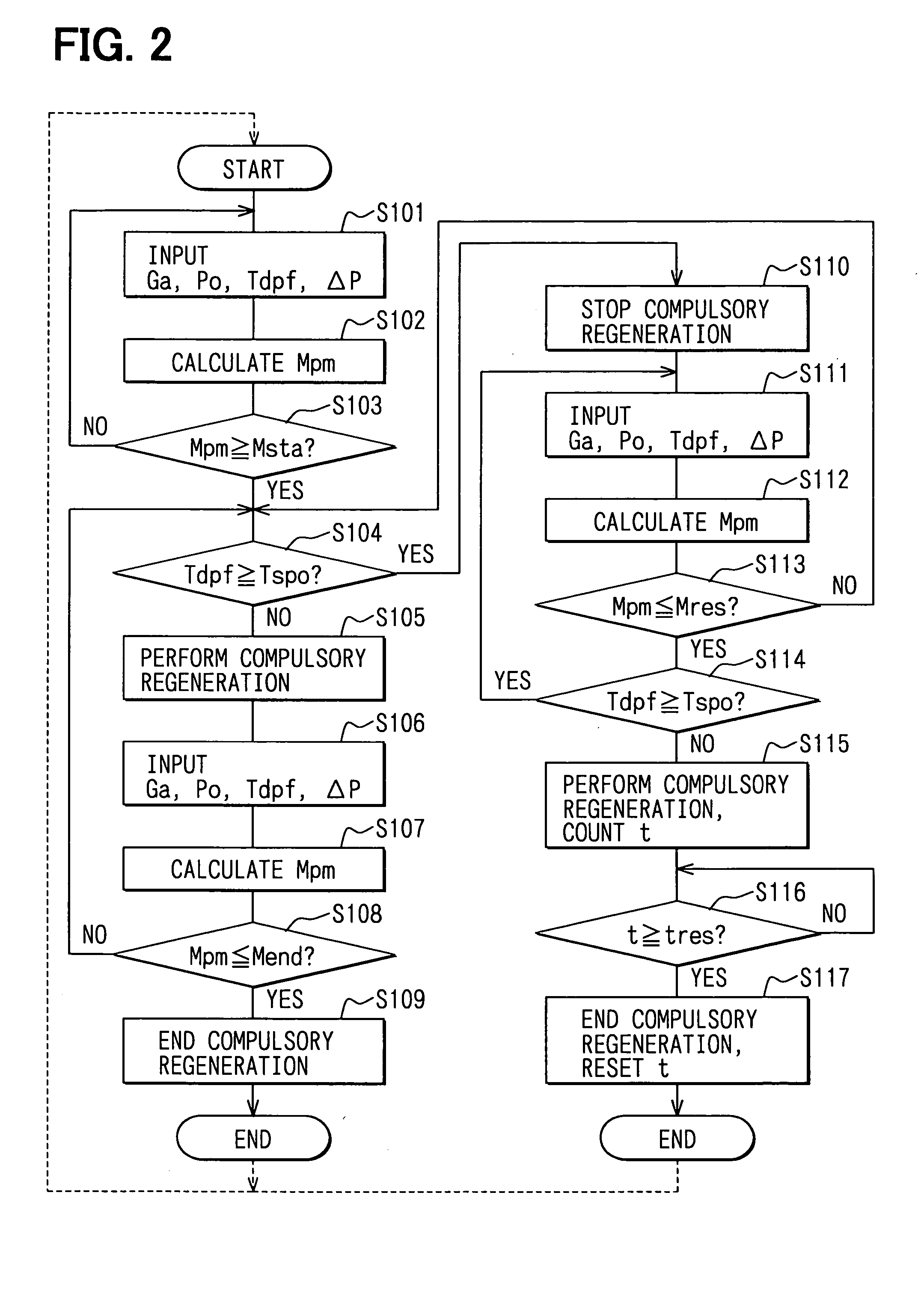
[0061] Next, steps of control performed by an ECU 51 of an exhaust gas purification system of an internal combustion engine according to a second embodiment will be explained based on a flowchart shown in FIG. 7.

[0062] The ECU 51 calculates the PM deposition quantity Mdpf like the first embodiment. If the PM deposition quantity Mdpf exceeds the regeneration start PM quantity Msta, the compulsory regeneration is started. The compulsory regeneration is continued until the PM deposition quantity Mpm decreases to the regeneration end PM quantity Mend except in a period in which the DPF temperature Tdpf is equal to or higher than the PM spontaneous regeneration temperature Tspo.

[0063] In Step S201 of the flowchart of FIG. 7, the intake air quantity Ga, the atmospheric pressure P0, the exhaust gas temperature Tdpf, an ambient temperature Ta and the DPF pressure loss ΔP are inputted.

[0064] Then, in Step S202, a temperature distribution in the DPF 32 is calculated based...

Example

Third Embodiment

[0080] Next, control steps performed by an ECU 51 of an exhaust gas purification system of an internal combustion engine according to a third embodiment of the present invention will be explained based on FIG. 10.

[0081] In Step S301, the intake air quantity Ga, the atmospheric pressure P0, the DPF temperature Tdpf, the ambient temperature Ta, and the DPF pressure loss ΔP are inputted as in Step S201 of the second embodiment. Then, in Step S302, the temperatures A-I in the respective spaces S1-S9 are calculated as in Step S202 of the second embodiment. Then, the combustion speeds Cpm in the respective spaces S1-S9 are calculated as in Step S203 of the second embodiment.

[0082] In Step S304, the PM deposition quantities mpm of the respective spaces S1-S9 of the DPF 32 are calculated and the maximum value among the PM deposition quantities mpm is selected as a maximum deposition portion PM deposition quantity mpm(max).

[0083] In Step S305, the maximum deposition porti...


PUM

PropertyMeasurementUnit
Temperatureaaaaaaaaaa
Speedaaaaaaaaaa
Deposition rateaaaaaaaaaa

Abstract

An electronic control unit (ECU) of an internal combustion engine calculates a present deposition quantity of exhaust particulate matters based on operating states of the engine such as a differential pressure of a diesel particulate filter (DPF). If the present deposition quantity exceeds a predetermined upper limit value, the ECU performs compulsory regeneration of the DPF to compulsorily combust and reduce the deposited exhaust particulate matters. The ECU determines that spontaneous regeneration occurs if a temperature of exhaust gas in the DPF is equal to or higher than a reference temperature. Thereafter, the ECU completes the compulsory regeneration to eliminate the deposited exhaust particulate matters if the ECU determines that the spontaneous regeneration stops and the deposition quantity becomes equal to or less than a predetermined lower limit value.

Description

CROSS REFERENCE TO RELATED APPLICATION [0001] This application is based on and incorporates herein by reference Japanese Patent Applications No. 2004-69981 filed on Mar. 12, 2004 and No. 2004-363993 filed on Dec. 16, 2004. BACKGROUND OF THE INVENTION [0002] 1. Field of the Invention [0003] The present invention relates to an exhaust gas purification system of an internal combustion engine having a particulate filter. Specifically, the present invention relates to a technology for regenerating the particulate filter at appropriate timing. [0004] 2. Description of Related Art [0005] In recent years, improvement of exhaust emission of internal combustion engines mounted to automobiles has been required. Specifically, in a compression ignition diesel engine, of which fuel is light oil, exhaust particulate matters contained in exhaust gas, such as soot or soluble organic fractions, should be reduced in addition to gasses of carbon monoxide, hydrocarbon, and nitrogen oxides. Therefore, a ...

Claims


Application Information

Patent Timeline
IPC IPC(8): F01N3/02B01D46/42B01D53/86B01D53/94F01N3/00F01N3/023F01N9/00F01N11/00
CPCF01N3/023F01N9/002Y02T10/47F01N11/005F01N13/008F01N11/002Y02T10/40
Inventor SAITOH, MAKOTOYAHATA, SHIGETOTOCHIKAWA, KAZUHARU
Owner DENSO CORP
Why Eureka
Try Eureka