Thermal management system and method for vehicle electrochemical engine

a technology of electrochemical engine and management system, which is applied in the direction of machines/engines, transportation and packaging, battery/fuel cell control arrangement, etc., to achieve the effect of reducing the required cooling airflow rate, reducing the airflow rate, and convenient packaging of radiators

Active Publication Date: 2005-09-15
GM GLOBAL TECH OPERATIONS LLC
View PDF20 Cites 35 Cited by
  • Summary
  • Abstract
  • Description
  • Claims
  • Application Information

AI Technical Summary

Benefits of technology

[0004] This invention greatly reduces the required cooling airflow rate by including the heat of water vaporization. The reduced airflow rate is accommodated in a much smaller, and therefore more easily packaged radiator by including evaporative cooling.

Problems solved by technology

Thermal management of an electrochemical engine presents several important considerations and challenges as compared to a conventional internal combustion engine.
However, due to the current size of the radiator, vehicle style has been strongly driven by the high rate of airflow required for cooling.

Method used


Image

  • Thermal management system and method for vehicle electrochemical engine
  • Thermal management system and method for vehicle electrochemical engine
  • Thermal management system and method for vehicle electrochemical engine

Examples


Embodiment Construction

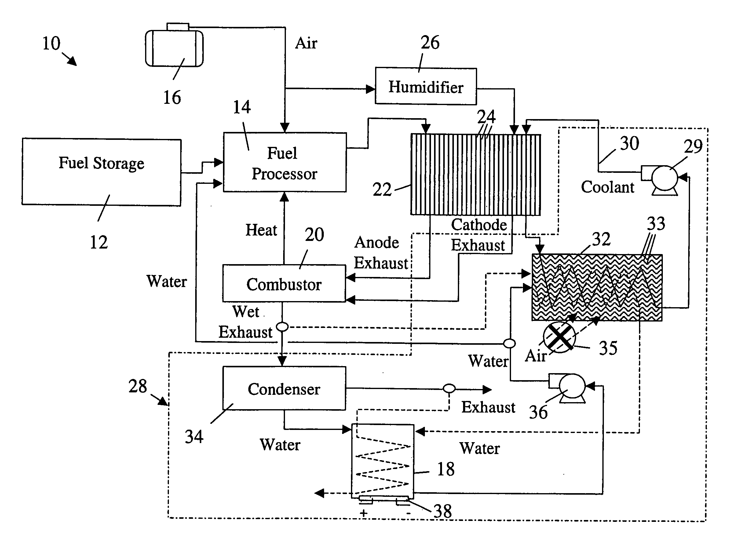
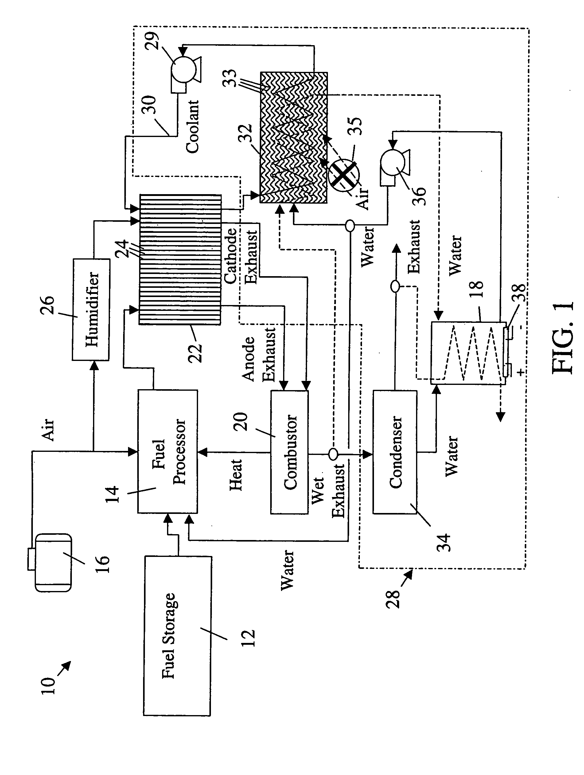
[0013] With reference to FIG. 1, an engine is generally indicated by symbol 10. In one embodiment, the engine 10 is an electrochemical engine (ECE), which operates to generate electricity in a fuel cell stack given two reactants, e.g., a hydrogenous gas and a gas containing oxygen. Hydrogenous gases for the fuel cell stack may be produced on board the vehicle and this method is described hereinafter; however, the present invention is not limited to such a system. In another embodiment, the engine 10 is a conventional internal combustion (IC) engine for vehicles that have limited radiator space.

[0014] In the illustrated embodiment, a liquid fuel, such as gasoline, diesel, methanol, etc., is stored on board the vehicle in a fuel tank 12. The fuel is supplied to a fuel processor 14 in the ECE 10. The fuel processor 14 may also receive compressed air from an air compressor 16 for partial oxidation and water, if available, from a water tank 18 for steam reformation. A combustor 20 gener...


PUM


Abstract

A thermal management system of an electrochemical engine comprises a radiator provided with a wicking mechanism, a coolant pump fluidly connected to the radiator, a water tank, and a water pump. The water tank is located in the void spaces around fuel storage tanks, and may be filled directly or with reclaimed water from a vapor by-product of the electrochemical engine. The water pump is operable to supply water from the water tank to the wicking mechanism during peak power and / or hot day conditions. Moisture in the vapor by-product may be condensed with the excess cooling capacity of the radiator under less severe cooling conditions. Under freezing conditions, exhaust or coolant from the electrochemical engine may be used to unfreeze water in the tank and wicking mechanism supply lines.

Description

FIELD OF THE INVENTION [0001] This invention relates to the field of thermal management and in particular, a thermal management system and method for an electrochemical engine used in a vehicle. BACKGROUND OF THE INVENTION [0002] Thermal management of an electrochemical engine presents several important considerations and challenges as compared to a conventional internal combustion engine. First, in an internal combustion engine, waste heat is managed about equally through both an exhaust gas stream and through a flow of air-cooled engine coolant. In comparison, an electrochemical engine manages most of its waste heat through air-cooled engine coolant. Second, an internal combustion engine typically operates at 120° C., where an electrochemical engine operates at the lower temperature of 80° C. Therefore, the heat transfer between the coolant and air in a thermal management system of an electrochemical engine is about one-half that of an internal combustion engine due to the smaller...

Claims


Application Information

Patent Timeline
Patent Type & Authority Applications(United States)
IPC IPC(8): B60L11/18F01P9/00
CPCB60L11/1892B60L2240/36Y02T10/642Y02T90/34B60L2240/425B60L58/33Y02T10/64Y02T90/40
Inventor GOEBEL, STEVEN G.FLY, GERALD W.SKALA, GLENN WILLIAMWHITEHEAD, LEE CURTIS
Owner GM GLOBAL TECH OPERATIONS LLC
Why Eureka
Try Eureka