EUV light source optical elements

Active Publication Date: 2005-09-15
ASML NETHERLANDS BV
View PDF21 Cites 72 Cited by
  • Summary
  • Abstract
  • Description
  • Claims
  • Application Information

AI Technical Summary

Benefits of technology

[0012] Apparatus and methods are disclosed for forming DPP or LPP plasma generated EUV light source optical elements, e.g., reflectors comprising MLM stacks employing various binary layer materials and capping layer(s) including si

Problems solved by technology

In the process of the creation of the plasma for the emission of EUV light several harsh results of the plasma creation are released into the environment in the EUV light source generation chamber around the plasma that are potentially very damaging to materials comprising, e.g., the collector/director optical element, e.g., heat, high energy ions and scattered debris from the plasma formation, e.g., atoms or clumps of source material not ionized in the plasma formation process.
The heat, high energy ions and/or source material may be damaging to the optical elements in a number of ways, including simply heating them, penetrating into them and, e.g., damaging s

Method used


Image

  • EUV light source optical elements
  • EUV light source optical elements
  • EUV light source optical elements

Examples


Embodiment Construction

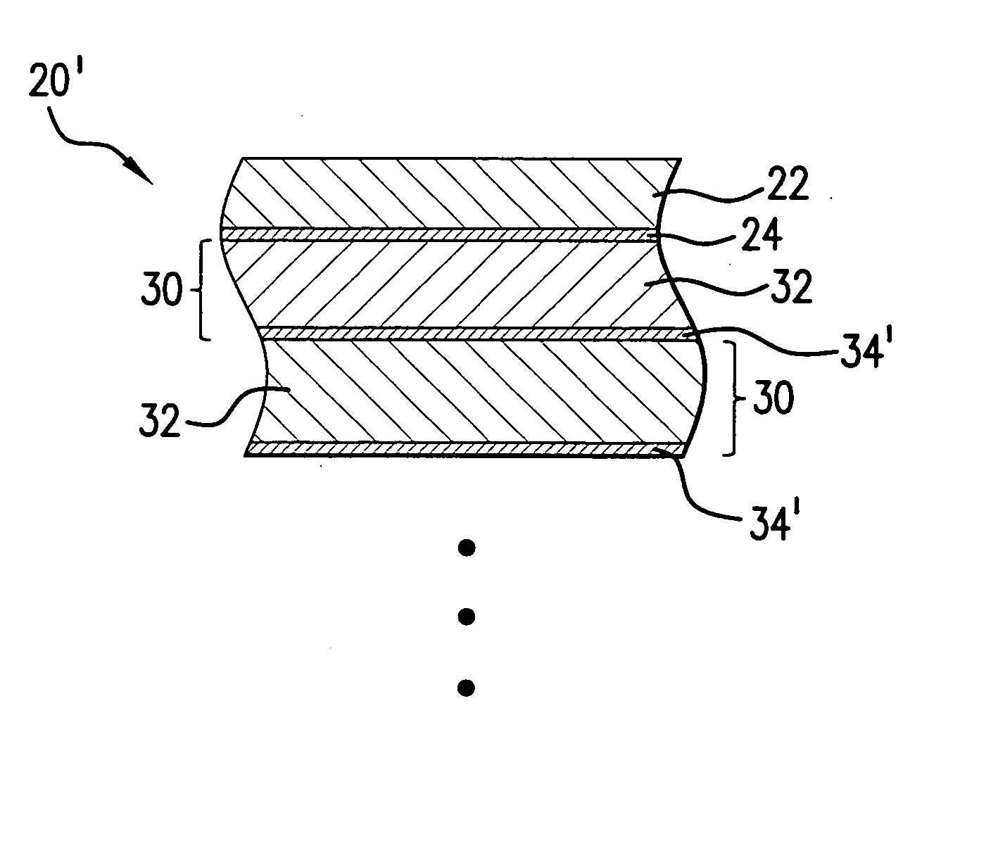
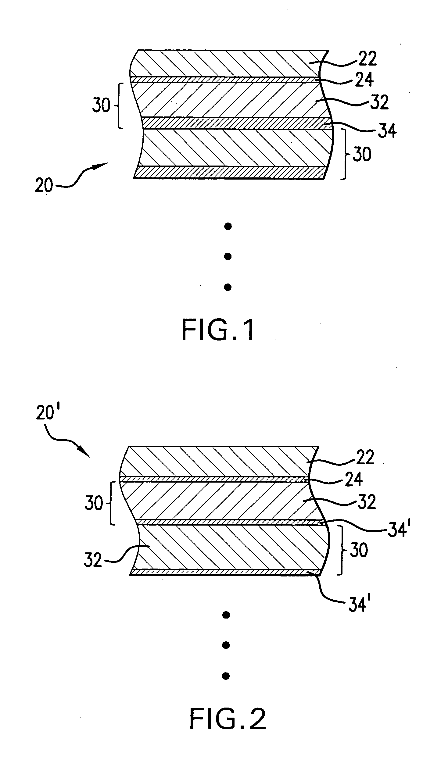
[0024] Turning now to FIG. 1 there is shown schematically and not to scale a prior art MLM 20 structure and composition including a ruthenium capping layer 22 and an underlying intermediate layer 24, which may be, e.g., a source material diffusion barrier layer 24, which may be selected for its resistance to diffusion of a selected material, or its compounds, e.g., the source material for the EUV plasma, e.g., lithium. The MLM 20 may comprise be made up of a plurality of binary layers 30 made up of an absorber layer, e.g., a molybdenum layer 32 and a spacer layer 34 e.g., of silicon.

[0025] Source material diffusion through the diffusion barrier layer 24 and into the binary layer(s) 30 and the formation between the layers 32 and 33 of a source material silicide, e.g., lithium silicide, which can cause, e.g., a roughness of the Mo and / or Si at the Mo / Si interface. This can detract from the binary layers 30 thermal stability at elevated temperatures, and also impact the reflectivity o...


PUM


Abstract

Apparatus and methods are disclosed for forming plasma generated EUV light source optical elements, e.g., reflectors comprising MLM stacks employing various binary layer materials and capping layer(s) including single and binary capping layers for utilization in plasma generated EUV light source chambers, particularly where the plasma source material is reactive with one or more of the MLM materials.

Description

FIELD OF THE INVENTION [0001] The present invention relates to extreme ultraviolet (“EUV”) light generators providing EUV light from a plasma created from a source material and collected and directed to a focus for utilization outside of the EUV light source generation chamber, e.g., for semiconductor integrated circuit manufacturing photolithography process performing machines, e.g., at wavelengths of around 20 nm and below. RELATED APPLICATIONS [0002] The present application is a continuation-in-part of U.S. Pat. Application Ser. No. 10 / 979,945, entitled LPP EUV LIGHT SOURCE, filed on Nov. 1, 2004, Attorney Docket No. 2004-0088-01, and Ser. No. 10 / 900,839, entitled EUV LIGHT SOURCE, filed on Jul. 27, 2004, Attorney Docket No. 2004-0044-01, and Ser. No. 10 / 803,526, entitled HIGH REPETITION RATE LPP EUV LIGHT SOURCE, filed on Mar. 17, 2004, Attorney Docket No. 2003-0125-01 and Ser. No. 10 / 798,740, entitled COLLECTOR FOR EUV LIGHT, filed on Mar. 10, 2004, Attorney Docket No. 2003-008...

Claims


Application Information

Patent Timeline
IPC IPC(8): G03F7/20G03F9/00G21K1/06
CPCB82Y10/00G21K1/062G03F7/70916G03F7/70175G03F7/20G03F9/00H01J35/20
Inventor BOWERING, NORBERT R.ERSHOV, ALEXANDER I.DYER, TIMOTHY S.GRINOLDS, HUGH R.
Owner ASML NETHERLANDS BV
Why Eureka
Try Eureka