Surface tracker

a tracker and surface technology, applied in the field of surface trackers, can solve the problems of inconductivity of most conduits, and inability to detect any surface instrumentation, and achieve the effects of long-term locatability, superior locating capability, and resistance to wear and tear and the elements

Inactive Publication Date: 2005-09-15
MINAROVIC JOE T
View PDF8 Cites 10 Cited by
  • Summary
  • Abstract
  • Description
  • Claims
  • Application Information

AI Technical Summary

Benefits of technology

[0016] It is yet another object of the present invention to provide an electronic marker which provides for long-term locatability.
[0017] The foregoing objects are achieved in a surface tracker generally comprising a tubular marker body having an electronic marker located inside an interior chamber, and a visual indicator attached to an upper end of the marker body which extends away from the marker body. In the illustrative implementation, the surface tracker is partially buried, with the marker body being mostly underground, while the visual indictor extends upwardly from the ground level to provide above-ground visual recognition. An end cap may be bonded to the lower end to seal an opening that allows insertion of the electronic marker. The electronic marker may be a passive electronic marker that includes a ferrite core assembly having a longitudinal axis which is generally parallel to a longitudinal axis of the marker body. The visual indicator may comprise a plurality of resilient filaments which pass through a hole in a tab portion of the marker body at the upper end thereof, the filaments being folded about the tab portion and secured to the tab portion using a heat-shrink tube. In an exemplary embodiment, the filaments extend about six inches from the marker body. Multiple trackers can be deployed to mark the path of a buried utility. Due to the resilient and durable nature of the filaments, they are resistant to wear and tear and the elements. The visual indication, along with the ability to electronically detect the marker, provides a tracker with superior locating capability.

Problems solved by technology

Above-ground marking devices may be installed immediately after the conduit is buried, but they are often lost, stolen, or destroyed after a short period of use.
The primary disadvantage of (non-metallic) warning tapes is that they cannot be detected by any surface instrumentation.
Although the conduit itself may act as a conductor (i.e., when steel pipe or copper wire cabling is used), most conduits are non-conductive and therefore require a trace wire.
There are three significant disadvantages in the use of a trace wire.
Secondly, if a break occurs in the wire (due to excavation, or natural causes such as corrosion, earth movement or burrowing animals), then the wire becomes useless.
Additionally, a receiver cannot distinguish the trace wire from any other conductor in the vicinity.
While several of the foregoing articles can be used to alert an excavation team that a buried object is nearby, there continue to be problems regarding both locating and damaging the cables or conduits.
Significantly, none of the foregoing designs offer any above-ground visual indication of the desired location, so a fair amount of trial and error searching must be performed before the signal from the subsurface marker is detected.
If there are several underground markers in the same general vicinity, it is very likely that the searcher will mistakenly identify one of the other markers as the target marker, resulting in a mislocate of the obscured object which is only revealed after the site has been excavated.
Although a location can be marked above-ground with stakes, paint, flags, etc., these implements can be removed or easily obscured by growth over time.
Stakes and flags can further be re-positioned at the surface so there is no guarantee that such an implement will still be marking the proper location at later dates.

Method used


Image

  • Surface tracker
  • Surface tracker
  • Surface tracker

Examples


Embodiment Construction

)

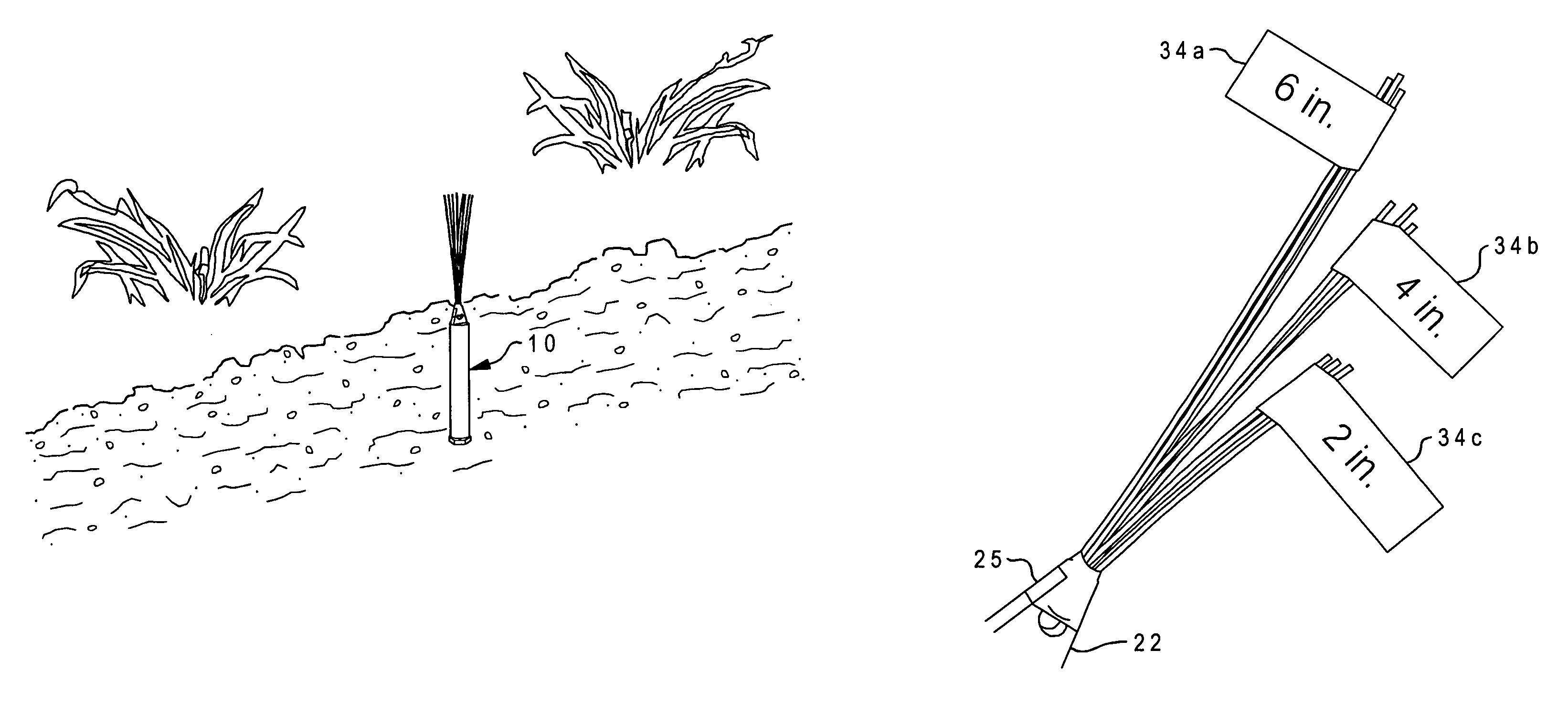
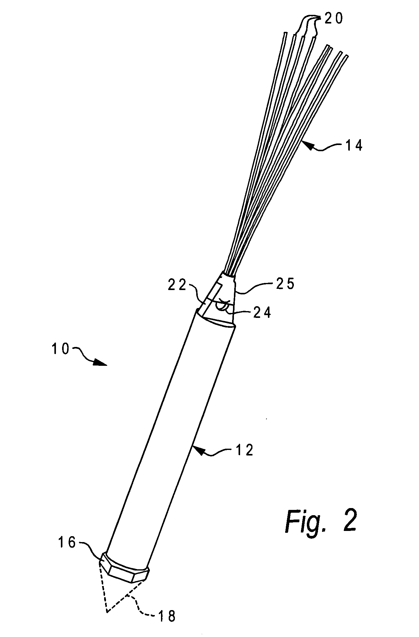
[0028] With reference now to the figures, and in particular with reference to FIGS. 2-4, there is depicted one embodiment 10 of a surface tracker constructed in accordance with the present invention. Surface tracker 10 is generally comprised of a marker body 12 and a visual indicator 14. In this embodiment, marker body 12 has a generally cylindrical (tubular) casing, and houses a passive electronic marker as discussed further below. A cap 16 at the lower end of marker body 12 is used to seal the end opening that receives the interior passive electronic marker. End cap 16 may optionally have a pointed (conical) protrusion 18 to facilitate the insertion of marker body 12 into the ground. End cap 16 may take the form of a screw plug having threads which mate with matching threads along the interior wall of marker body 12. Marker body 12 and end cap 16 may be formed of any durable material, particularly a moldable polymer such as polyethylene. Marker body 12 may be constructed using in...


PUM


Abstract

A surface tracker includes a tubular marker body having an interior electronic marker and a visual indicator attached to an upper end of the marker body which extends away from the marker body. When deployed, the marker body is mostly underground and the visual indictor extends upwardly from the ground level to provide above-ground visual recognition. The electronic marker may be a passive electronic marker that includes a ferrite core assembly having a longitudinal axis which is generally parallel to a longitudinal axis of the marker body. The visual indicator may be a plurality of resilient filaments which pass through a hole in a tab portion of the marker body at the upper end thereof, the filaments being folded about the tab portion and secured to the tab portion using a heat-shrink tube. In an exemplary embodiment, the filaments extend about six inches from the marker body and are brightly colored. Multiple trackers can be used to mark the path of a buried utility. Due to the resilient and durable nature of the filaments, they are resistant to wear and tear and the elements. The visual indication, along with the ability to electronically detect the marker, provides a tracker with superior locating capability.

Description

BACKGROUND OF THE INVENTION [0001] 1. Field of the Invention [0002] The present invention generally relates to devices used to electromagnetically mark and locate obscured objects, and more particularly to a surface tracker adapted to visually mark a buried object or a location at the surface or ground level, which also provides a transponder or marker to enable the later location of the tracker when it becomes buried. [0003] 2. Description of the Related Art [0004] Buried conduits are employed for supplying a wide variety of utilities, including pipelines for gas, water and sewage, and cables for telephone, optical fiber, power and television. It often becomes necessary to locate defective or damaged cables, pipes, etc., in order to repair or replace them. Conversely, it is important to know with as much accuracy as possible the approximate vicinity of such items in order to avoid disturbing them when digging or excavating for other purposes. Above-ground marking devices may be ins...

Claims


Application Information

Patent Timeline
Patent Type & Authority Applications(United States)
IPC IPC(8): G08B13/14
CPCG01V15/00
Inventor MINAROVIC, JOE T.
Owner MINAROVIC JOE T
Why Eureka
Try Eureka