Method for modification of radiotherapy treatment delivery

Active Publication Date: 2005-09-15
TOMOTHERAPY INC
View PDF99 Cites 144 Cited by
  • Summary
  • Abstract
  • Description
  • Claims
  • Application Information

AI Technical Summary

Benefits of technology

[0021] A primary benefit of MMODS is that it does not require reoptimization. Instead, several approved plans are available, and for each fraction an appropriate delivery plan is chosen. While MMODS can function independently of CADR, they are also well suited to work in tandem. For example, an improved patient positioning indicated by CADR may allow the selection of a plan with smaller margins than otherwise needed. Or if larger margins are desired, CADR may help accommodate that without additional harm to sensitive structures.
[0022] The MMODS embodiment provides multi-margin optimization with daily selection without the need for reoptimization or daily contouring. Instead of selecting a single planning target volume (PTV) margin that wi

Problems solved by technology

Due to anatomical changes caused by tumor growth, breathing, organ movement or the like, the intended structures may not receive the planned dose, even if the radiation therapy machine operates perfectly.
For example, the motion of target structures relative to sensitive structures could cause underdosing or overdosing of those structures, respectively.
However, this process is not generally fast enough to be performed on-line while the patient is on the treatment couch waiting to be treated.
However, because the patient cannot remain motionless on the treatment couch for too long, this process is typically not fast enough, as any movement ul

Method used


Image

  • Method for modification of radiotherapy treatment delivery
  • Method for modification of radiotherapy treatment delivery
  • Method for modification of radiotherapy treatment delivery

Examples


Embodiment Construction

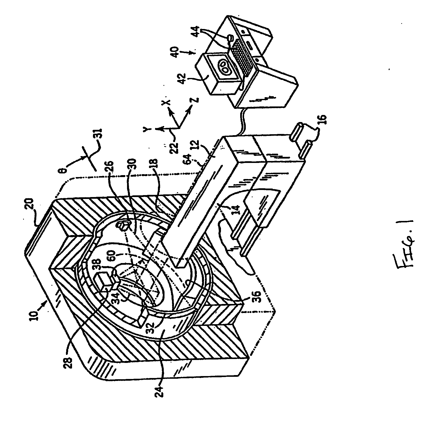
[0041] Referring now to FIG. 1, a radiation therapy machine 10, suitable for use with the present invention, includes a radiotranslucent table 12 having a cantilevered top 14. The table top 14 is received within a bore 18 of an annular housing 20 of the radiation therapy machine 10 with movement of the table 12 along tracks 16 extending along a z-axis of a Cartesian coordinate system 22.

[0042] Table 12 also includes an internal track assembly and elevator (not shown) to allow adjustment of the top 14 in a lateral horizontal position (indicated by the x-axis of the coordinate system 22) and vertically (indicated by the y-axis of the coordinate system 22). Motion in the x and y directions are limited by the diameter of the bore 18.

[0043] A rotating gantry 24, coaxial with the bore 18 and positioned within the housing 20, supports an x-ray source 26 and a high energy radiation source 28 on its inner surface. The x-ray source 26 may be a conventional rotating anode x-ray tube, while t...


PUM


Abstract

The present invention provides a novel method of contoured-anatomy dose repositioning (CADR) as a means to automatically reposition a patient to better recover the planned dose distribution without reoptimize the treatment plan. Specifically, CADR utilizes planning CT images, the planned dose distribution, and on-line images for repositioning dose distribution on a given day. Contours are also placed upon the images using manual, automatic, template-based, or other techniques. CADR then optimizes the rigid-body repositioning of the patient so that the daily dose distribution closely matches the planned dose distribution. The present invention also provides a method of multiple-margin optimization with daily selection (MMODS) to improve radiation delivery without reoptimization. During the initial optimization procedure, plans are optimized for several margins of various contours (e.g., tight, medium, loose, etc.), or with different objectives (e.g., aggressive treatment, sensitive structure sparing, etc.). Similarly, if multiple patient image sets are available, plans can be optimized for the different anatomical layouts, either using current information, or accumulated information regarding the superposition of organ locations in the combination of images. A user can then choose in real time from a variety of optimized plans, generally with different margins, during the treatment process, and thereby compensate for a recognized change in size or position of the tumor or neighboring tissue.

Description

CROSS-REFERENCE TO RELATED APPLICATIONS [0001] This application claims the benefit of U.S. Provisional Application No. 60 / 362,112, filed Mar. 6, 2002, the disclosure of which is incorporated herein by reference.BACKGROUND OF THE INVENTION [0002] This invention relates generally to intensity modulated radiation therapy for the treatment of cancer or the like, and specifically to a method for precisely delivering the dose of radiation to a displaced target. [0003] Medical equipment for radiotherapy treats tumorous tissue with high energy radiation. The amount of radiation and its placement must be accurately controlled to ensure that the tumorous tissue receives sufficient radiation to be destroyed, and that the damage to the surrounding and adjacent non-tumorous tissue is minimized. [0004] The radiotherapy process typically involves treatment planning and treatment delivery. The radiotherapy process commonly begins with the acquisition of three-dimensional patient images, such as a c...

Claims


Application Information

Patent Timeline
IPC IPC(8): A61NA61N1/00A61N5/10G06T1/00
CPCA61N5/103A61N5/1038A61N2005/1061A61N5/1067A61N5/1069A61N5/1065
Inventor RUCHALA, KENNETH J.OLIVERA, GUSTAVO H.KAPATOES, JEFFREY M.RECKWERDT, PAUL J.LU, WEIGUOHUGHES, JOHN H.
Owner TOMOTHERAPY INC
Why Eureka
Try Eureka