Process for determination of optimized exposure conditions for transverse distortion mapping

a technology of exposure conditions and mapping, applied in the field of optical metrology, can solve the problems of reducing the overall focus budget, difficult control of lithography processes, and various sources of overlay errors for both targets and patterned features, so as to reduce large feature shifts and accurately determine zernike terms a2

Inactive Publication Date: 2005-09-15
LITEL INSTR
View PDF11 Cites 18 Cited by
  • Summary
  • Abstract
  • Description
  • Claims
  • Application Information

AI Technical Summary

Benefits of technology

[0023] Illumination source conditions for the accurate determination of Zernike tilt coefficients in the presence of coma are described. Overlay alignment attribute-specific feature-shift coma sensitivity is simulated for a range of illumination conditions. The resulting source sensitivity data is modeled and a practical array of source shapes, each of which is optimized to eliminate the effects of transverse distortion due to third-order coma, is identified. The optimized set of source shapes can be used to more accurately determine Zernike terms a2 and a3 from lens distortion data (DX, DY). Knowledge of the lens distortion data in the absence of coma induced shifts can be entered into more traditional overlay regression routines to better identify systematic and random error or used to design better slot geometries during scanner assembly (see FIG. 4a). Additional applications of the above outlined process include: improved lithographic simulation using conventional optical modeling software, advanced process control in the form of feedback loops that automatically adjust the projection lens for optimum system performance.
[0024] In one aspect, a process for providing illumination conditions for accurate determination of Zernike tilt coefficients in the presence of t

Problems solved by technology

High NA lithography (including immersion lithography) has led to improved resolution and a reduction in the overall focus budget, making lithography processes difficult to control.
There are various sources of overlay error for both targets and patterned features.
Photolithographic imaging systems are often pushed to and beyond performance limits.
As the critical dimensions of semiconductor devices appro

Method used


Image

  • Process for determination of optimized exposure conditions for transverse distortion mapping
  • Process for determination of optimized exposure conditions for transverse distortion mapping
  • Process for determination of optimized exposure conditions for transverse distortion mapping

Examples


embodiment

Preferred Embodiment

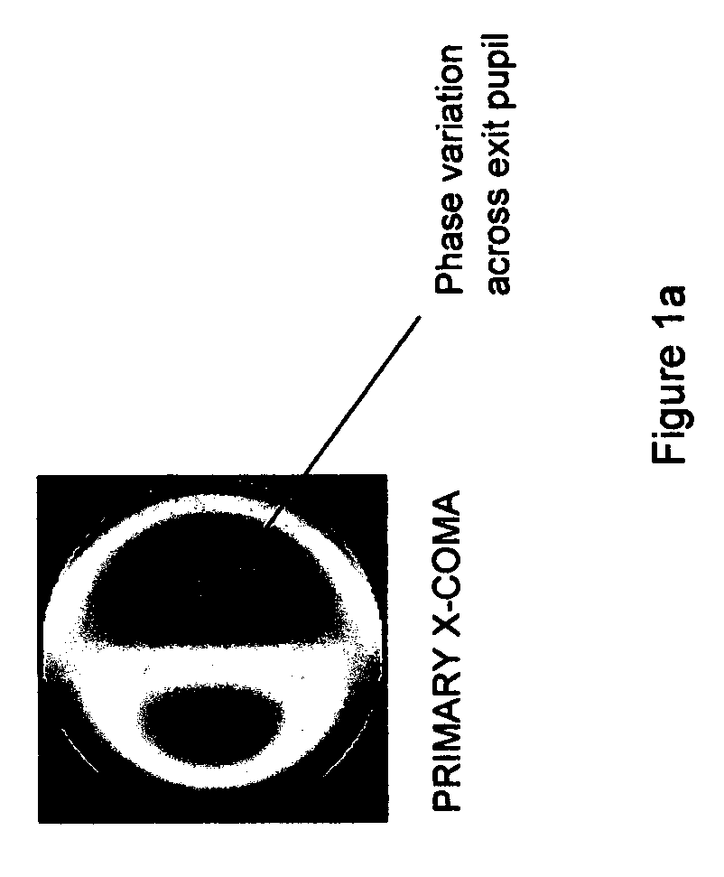
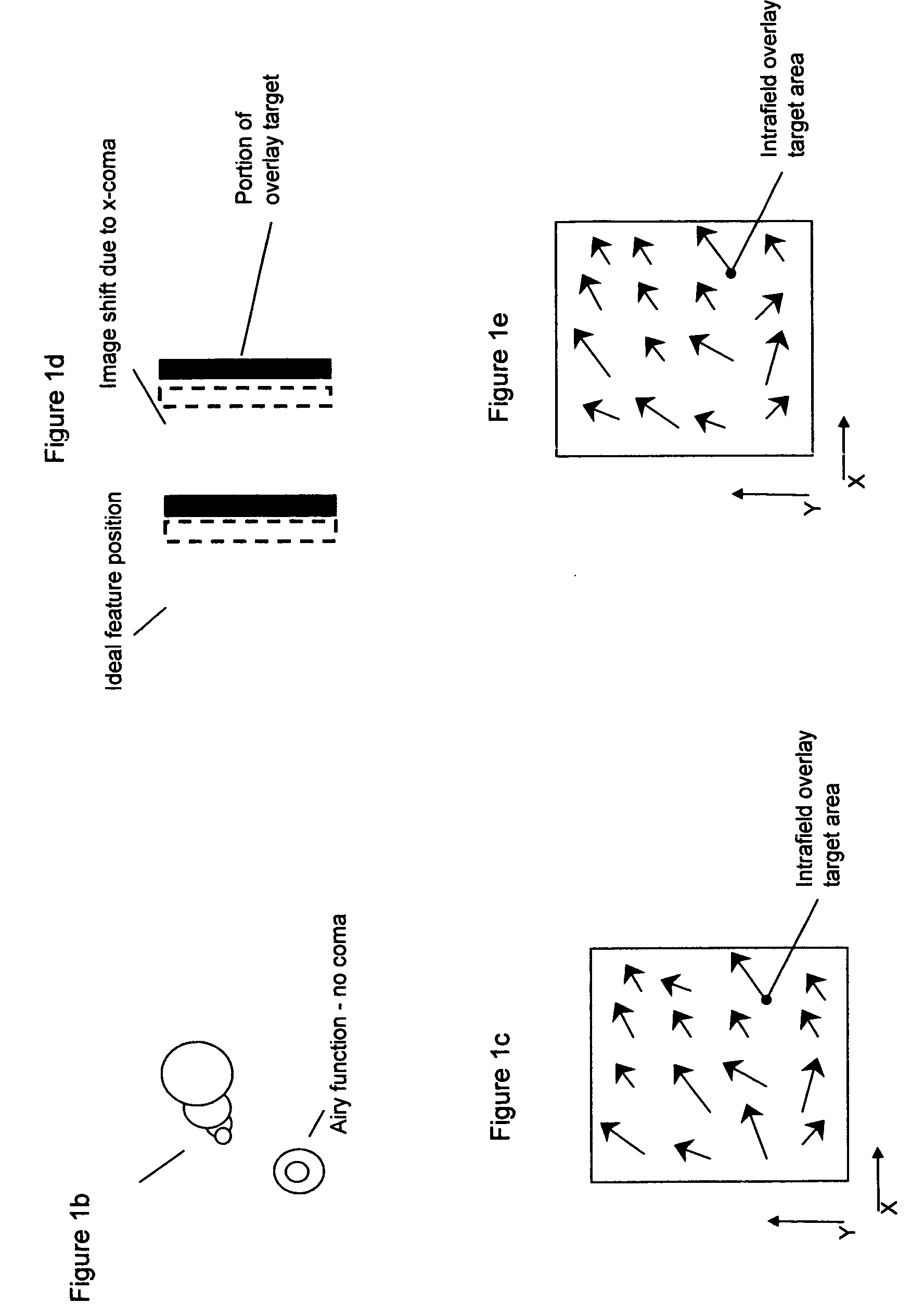
[0065] A particular process for providing an illumination source for the accurate determination of Zernike tilt coefficients in the presence of coma in accordance with the invention is described. Large feature-shift coma sensitivity is simulated for a range of illumination conditions. The resulting source sensitivity data is modeled and a practical array of source shapes, each of which is optimized to eliminate the effects of transverse distortion due to third-order coma, is identified. In this way, the present invention provides a process for providing an illumination source for which the effects of coma (third-order) on overlay alignment attributes feature-shift are eliminated, and lays out the details to calculate a2 and a3 more accurately using a photolithographic exposure tool and a variety of distortion measurement methods. Before describing the step-by-step process for the preferred embodiment and practical applications, we formulate third-order coma in te...


PUM


Abstract

A process for providing illumination source conditions for the accurate determination Zernike tilt coefficients in the presence of coma is described. Large feature-shift coma sensitivity is simulated for a range of illumination conditions. The resulting source sensitivity data is modeled and a practical array of source shapes, each of which is optimized to eliminate the effects of transverse distortion due to third-order coma, is identified. The optimized set of source shapes can be used to more accurately determine Zernike terms a2 and a3 using a variety of methods. Knowledge of the lens distortion data in the absence of coma induced shifts can be entered into more traditional overlay regression routines to better identify systematic and random error. Additional applications of the above outlined procedure include: improved lithographic simulation using conventional optical modeling software and advanced process control in the form of feedback loops that automatically adjust the projection lens for optimum system performance.

Description

BACKGROUND OF THE INVENTION [0001] 1. Field of the Invention [0002] The present invention relates generally to optical metrology and more particularly to methods for the determination of intra-field distortion and lens aberrations for projection imaging systems used in semiconductor manufacturing. [0003] 2. Description of the Related Art [0004] Semiconductor manufacturers and lithography tool vendors have been forced to produce higher numerical aperture (NA) lithography systems (steppers or scanners) using smaller wavelengths (for example, 193 nm DUV lithography) in response to the semiconductor industry's requirement to produce ever-smaller critical features. See, for example, the statement of the well-known “Moore's Law” at “Cramming More Components Onto Integrated Circuits”, G. Moore, Electronics, Vol. 38, No. 8, 1965. The ability to produce (manufacture) sub-wavelength features can often be determined by considering the rather simple (3-beam) Rayleigh scaling Resolution (R) and ...

Claims


Application Information

Patent Timeline
IPC IPC(8): G03B27/00G03C5/00G03F7/20
CPCG03F7/701G03F7/70633G03F7/706G03F7/705
Inventor SMITH, ADLAI H.BENDIK, JOSEPHHUNTER, ROBERT O. JR.
Owner LITEL INSTR
Why Eureka
Try Eureka