
Common radio architecture for multi-mode multi-band applications

Inactive Publication Date: 2005-09-15
SAMSUNG ELECTRONICS CO LTD
View PDF12 Cites 28 Cited by
  • Summary
  • Abstract
  • Description
  • Claims
  • Application Information

AI Technical Summary

Benefits of technology

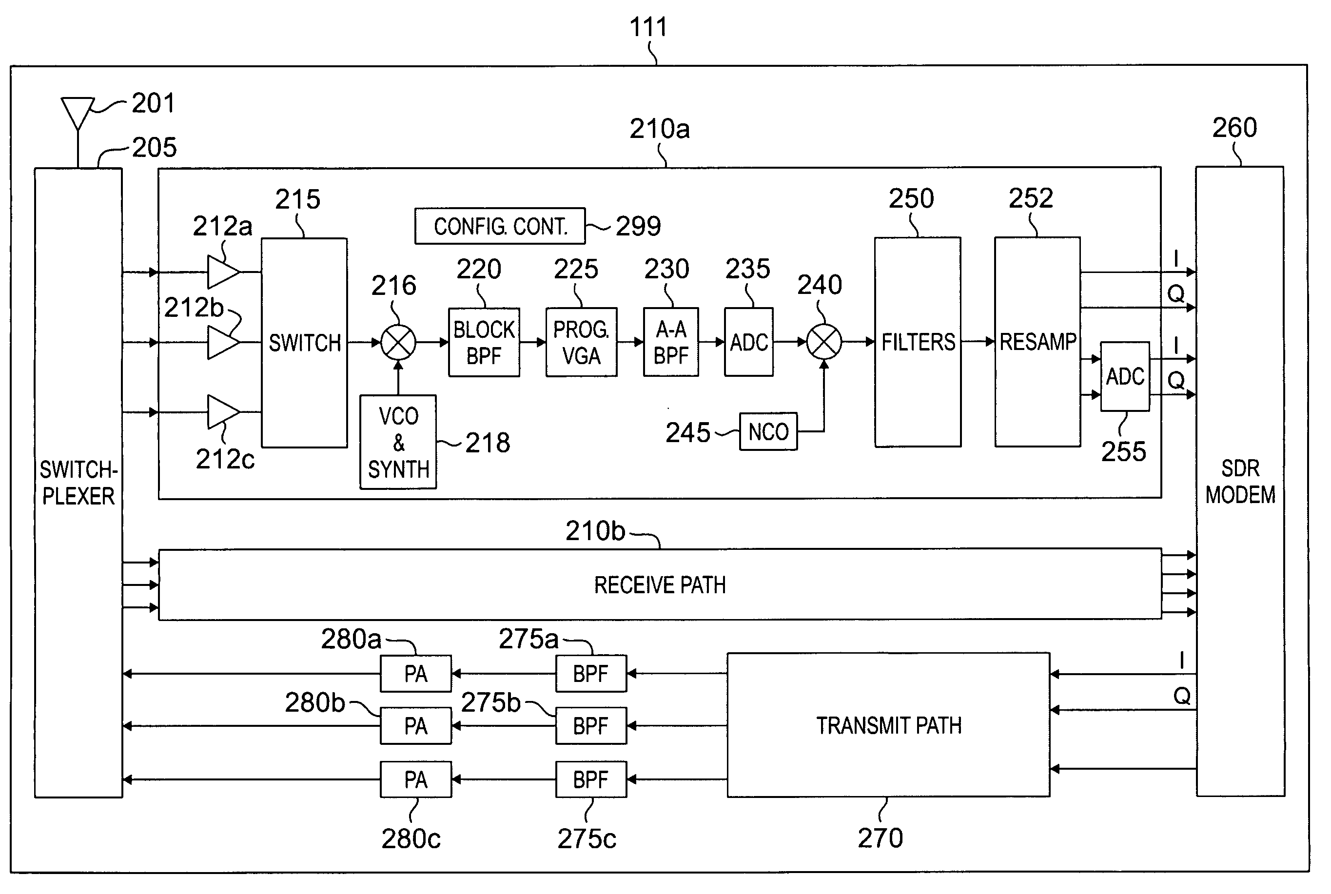
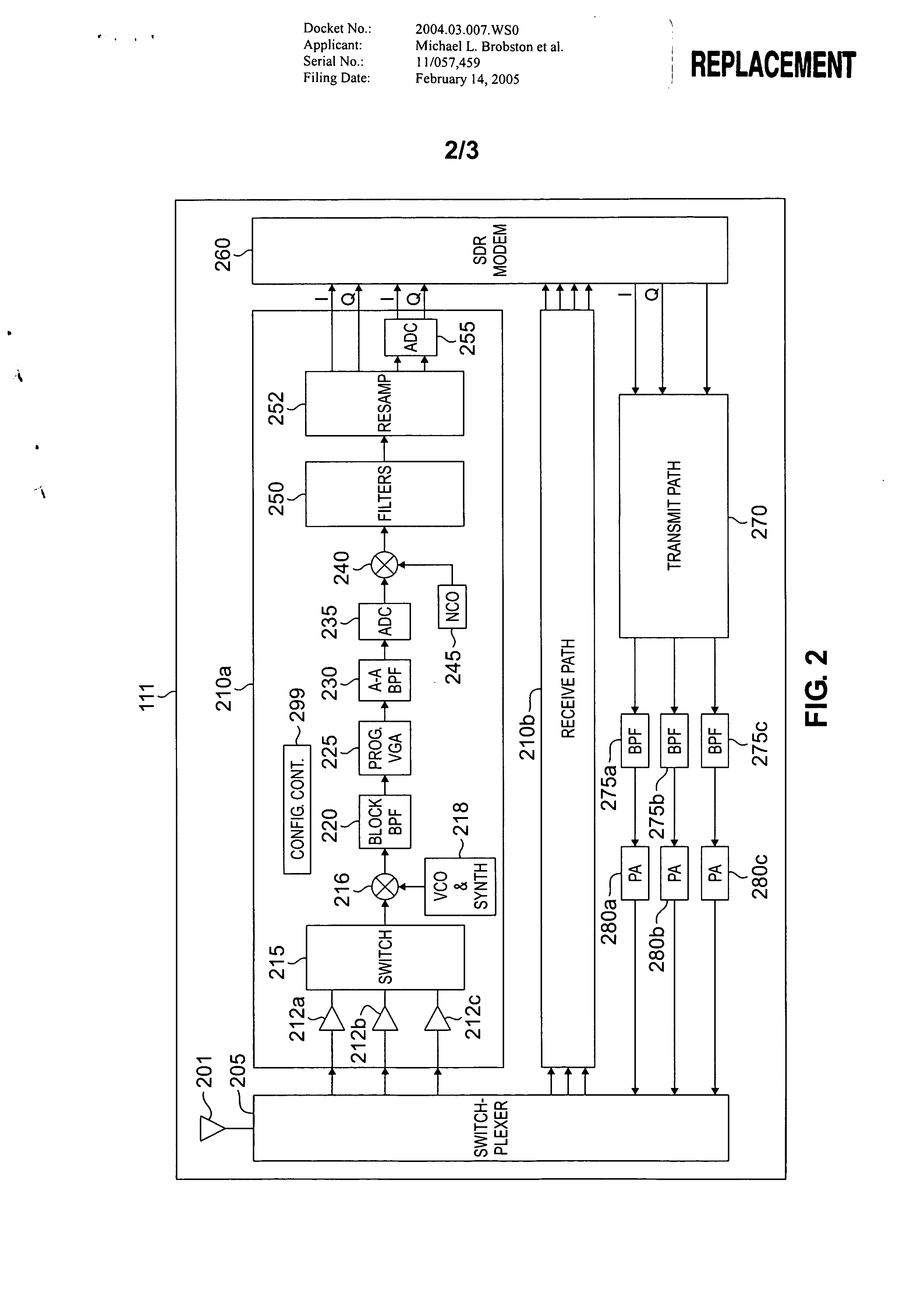
[0008] The present invention provides an apparatus for reducing the power consumption of the soft-ware defined radio (SDR) processing elements in a multi-mode, multi-band mobile station. The present invention accomplishes this using a Near Zero-Intermediate Frequency (NZIF) radio-frequency (RF) receiver front-end configuration that achieves a lower intermediate frequency (IF) and reduces the processing rate of the digital intermediate frequency (DIF) receiver component. The NZIF RF receiver provides a lower sampling rate at IF, while maintaining the digital signal processing functions at the IF level.
[0009] The present invention exploits a broad bandwidth image reject mixer design in the RF analog front-end of the receiver to cater to multiple frequency bands at lower current consumption. The present invention also exploits the configurability of the digital IF filters and operating the digital IF sections at lower sampling rates, thereby lowering current consumption.

Problems solved by technology

However, the proliferation of wireless access standards has proven to be inconvenient and challenging for the manufacturers of wireless mobile stations (or terminal), such as cell phones, PDA devices, wireless laptops, and the like.
End-user expectations of a ubiquitous network cannot be met with mobile stations that support only a subset of the possible standards.
However, the need for faster processing generally requires higher power.
However, the general trend is that current consumption increases as speed increases.
Such a configuration makes it impractical for the receiver to measure the received signal strength for use by the baseband modem.
Also, in conventional ZIF architectures, the direct down-converter is a narrowband device that is unsuitable for broadband applications.
Other receiver designs digitize at IF frequencies, which results in higher current (i.e., power) requirements.
The implementation of configurable hardware for conventional analog-to-digital components at higher frequencies proved too demanding on the current consumption budget.

Method used


Image

  • Common radio architecture for multi-mode multi-band applications
  • Common radio architecture for multi-mode multi-band applications
  • Common radio architecture for multi-mode multi-band applications

Examples


Embodiment Construction

[0021]FIGS. 1 through 3, discussed below, and the various embodiments used to describe the principles of the present invention in this patent document are by way of illustration only and should not be construed in any way to limit the scope of the invention. Those skilled in the art will understand that the principles of the present invention may be implemented in any suitably arranged multi-mode, multi-band mobile station.

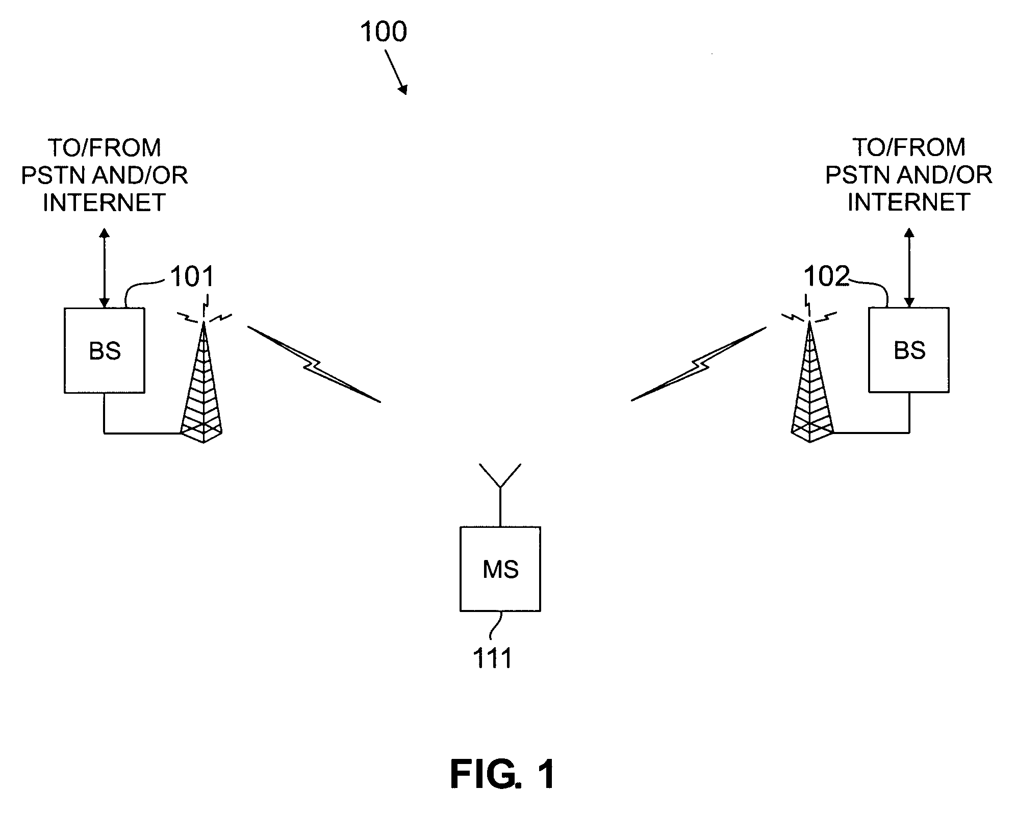
[0022]FIG. 1 illustrates wireless communication system 100, in which multi-mode, multi-band mobile station (or wireless terminal) 111 may communicate with base stations operating under different air interface standards. In FIG. 1, it is assumed that base station 101 is part of a first wireless network operating according to a first air interface standard (e.g., CDMA2000 in this example). It is further assumed that base station 102 is part of a second wireless network operating according to a second air interface standard (e.g., GSM in this example). Mobile statio...


PUM


Abstract

A multi-mode, multi-band mobile station for use in wireless networks operating under different air interface standards. The present invention, the mobile station comprises a plurality of low-noise amplifiers. Each of the plurality of low-noise amplifiers is optimized for use in a selected frequency band. The mobile station also comprises a near-zero intermediate frequency (NZIF) broadband image rejection mixer for receiving an amplified RF signal from a selected one of the plurality of low-noise amplifiers and down-converting the amplified RF signal to produce a first analog intermediate frequency (IF) signal.

Description

CROSS-REFERENCE TO RELATED APPLICATIONS [0001] The present invention is related to that disclosed in U.S. Provisional Patent Application Ser. No. 60 / 553,104, filed Mar. 13, 2004, entitled “Common Radio Architecture for Multi-Mode / Multi-Band Applications”. U.S. Provisional Patent Application Ser. No. 60 / 553,104 is assigned to the assignee of the present application. The subject matter disclosed in U.S. Provisional Patent Application Ser. No. 60 / 553,104 is hereby incorporated by reference into the present disclosure as if fully set forth herein. The present invention hereby claims priority under 35 U.S.C. §119(e) to U.S. Provisional Patent Application Ser. No. 60 / 553,104. TECHNICAL FIELD OF THE INVENTION [0002] The present invention relates generally to wireless networks and, more specifically, to a multi-mode, multi-band mobile station for use in a wireless network. BACKGROUND OF THE INVENTION [0003] Recent years have seen the deployment of a variety of different access standards for...

Claims


Application Information

Patent Timeline
IPC IPC(8): H04B1/00H04B1/10H04B17/40
CPCH04B1/006
Inventor BROBSTON, MICHAEL L.KIM, SEONG E.LOH, LUP M.
Owner SAMSUNG ELECTRONICS CO LTD
Learn More