Locomotive engine emission control and power compensation

Active Publication Date: 2005-09-22
GE GLOBAL SOURCING LLC
View PDF22 Cites 0 Cited by
  • Summary
  • Abstract
  • Description
  • Claims
  • Application Information

AI Technical Summary

Benefits of technology

[0018]FIG. 6 is a three-dimensional chart plotting brake specific NOx (BSNOx), brake specific particulate matter (BSPM), and brake specific fuel consumption (BSFC) for a nominal set of engine operating conditions, and illustrating the effect of retarding the start of fuel injection (SOI), as compared to the nominal conditions;
[0019]FIG. 7 is a chart similar to FIG. 6 illustrating the effect of lowering intake manifold air temperature;
[0020]FIG. 8 i

Problems solved by technology

For example, retarding fuel injection timing, which ef

Method used


Image

  • Locomotive engine emission control and power compensation
  • Locomotive engine emission control and power compensation
  • Locomotive engine emission control and power compensation

Examples


Embodiment Construction

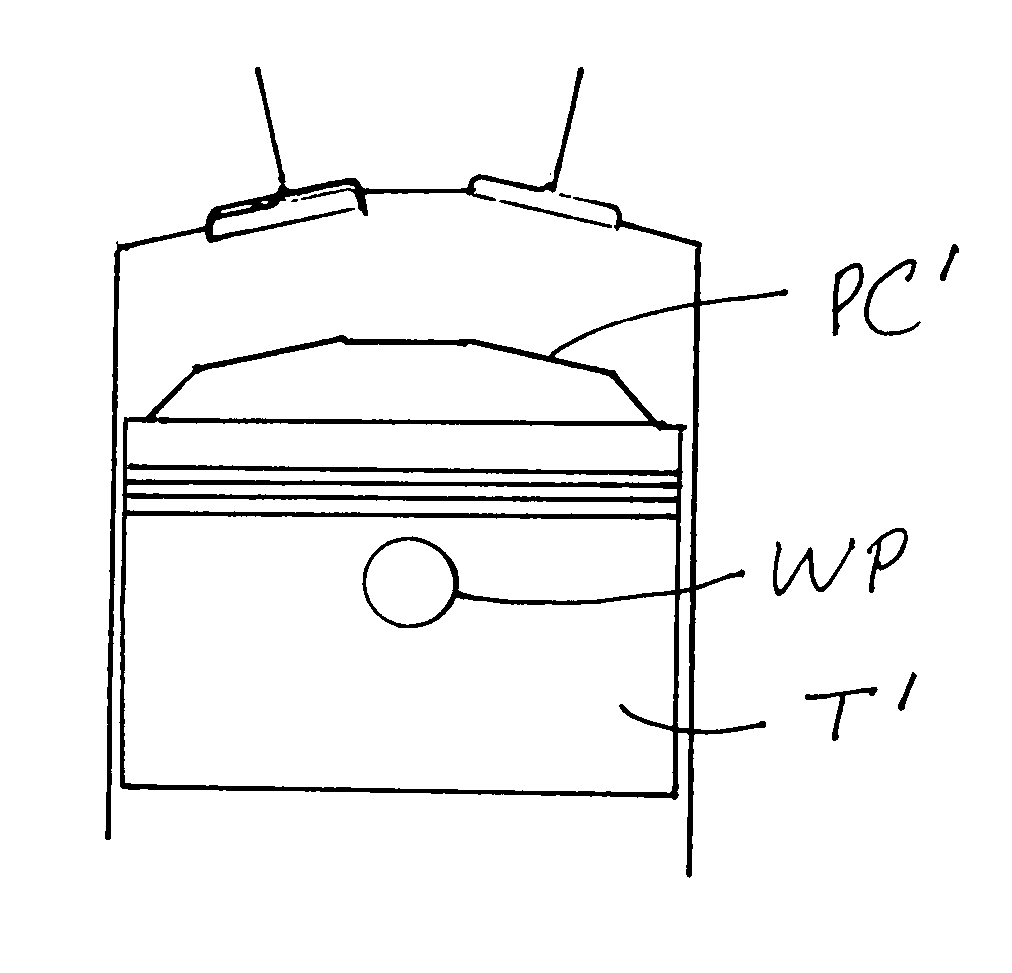
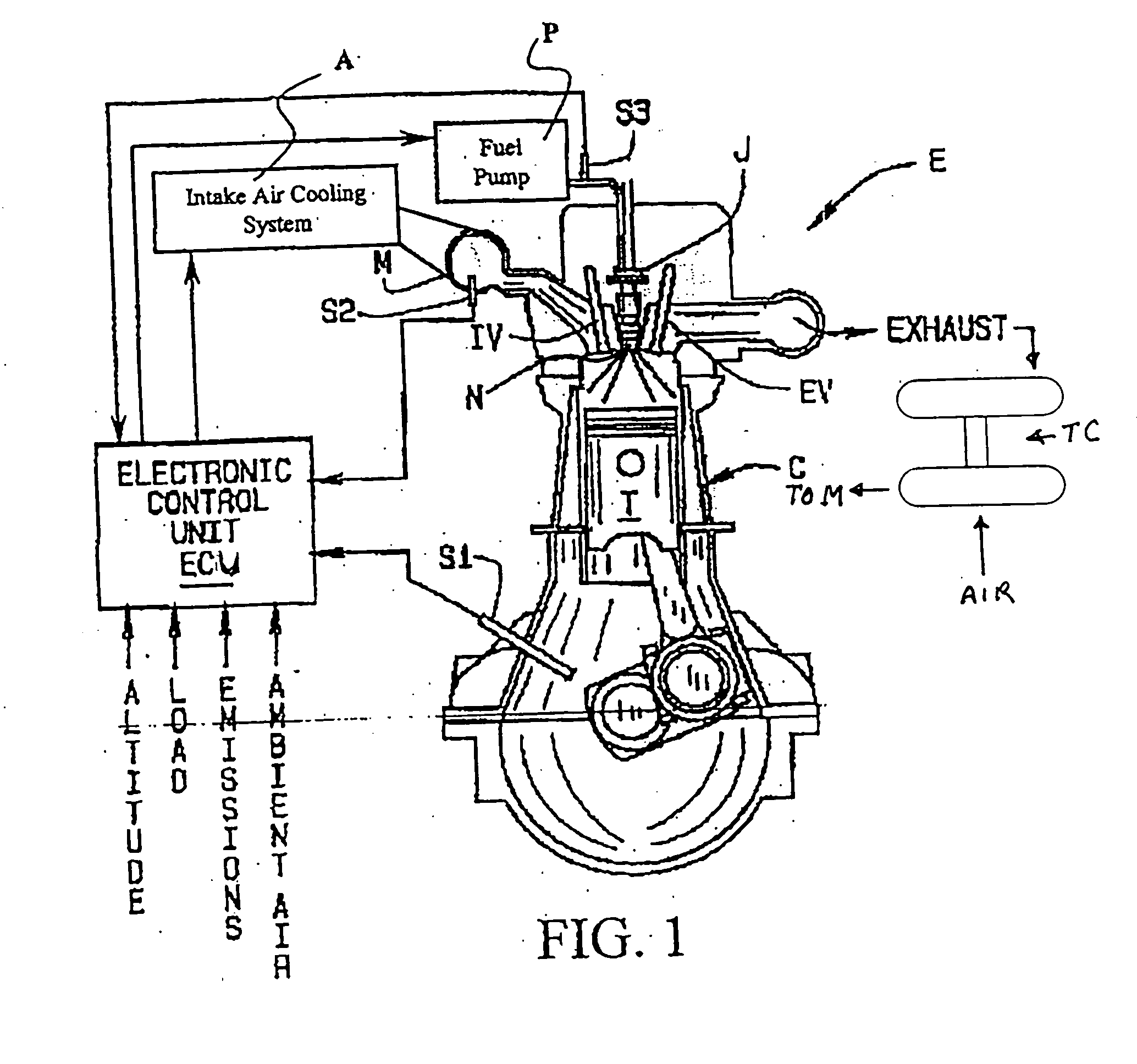
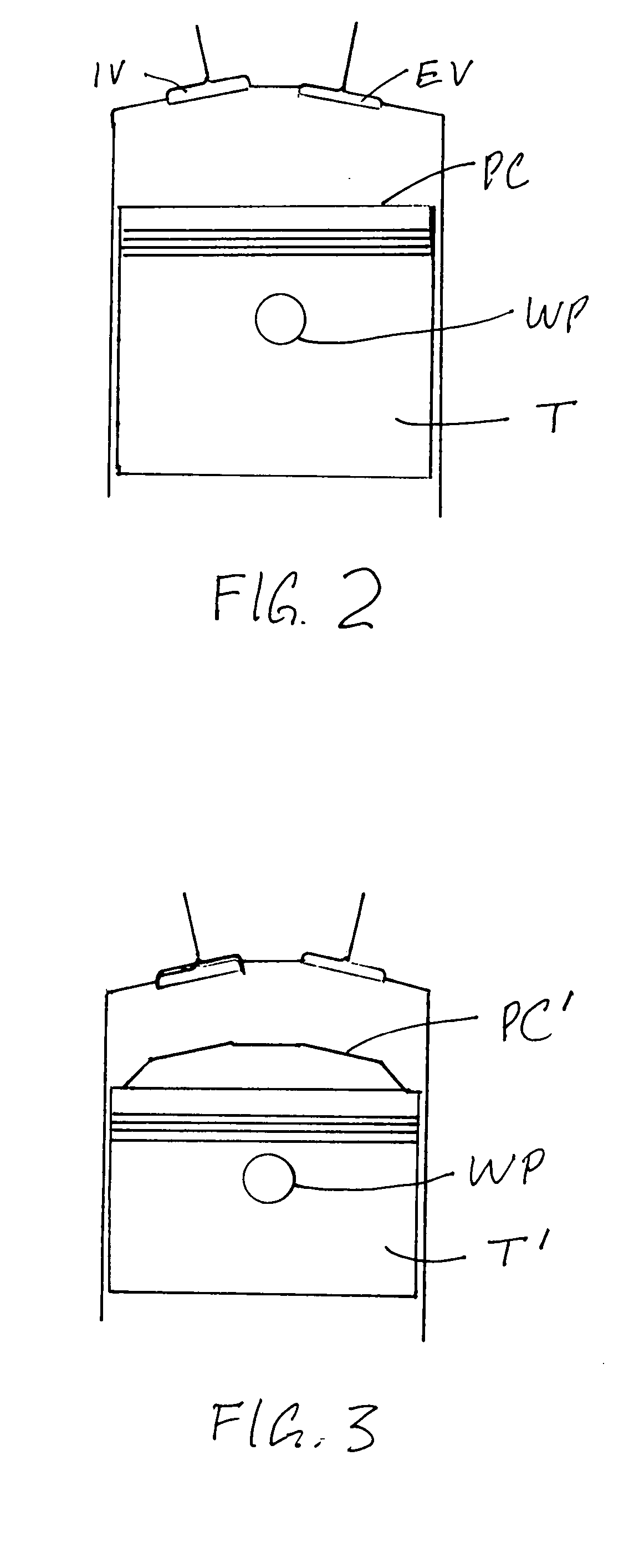
[0022] Referring to the drawings, a diesel engine E has a plurality of combustion chambers or cylinders C, only one of which is shown in FIG. 1. As is well known in the art, air at an elevated temperature flows through an intake manifold M and is drawn into the combustion chamber through an intake valve IV and compressed by movement of a piston T. Air temperature in the intake manifold M is controlled by an intake air cooling system A which includes, for example, an aftercooler and a fluid coolant (not shown). Functions such as injection timing could be controlled by an electronic control unit as shown, or they could be controlled mechanically through the use of apparatus which is known in the art. Air pressure in the intake manifold M is increased by an exhaust driven turbocharger TC. Fuel supplied by a fuel pump P is injected into the combustion chamber through the nozzle N of an injector J and the resulting air / fuel mixture is burned. The products of combustion are then exhausted...


PUM


Abstract

A method and apparatus for lowering NOx in diesel engine exhaust gases while maintaining thermal efficiency, by retarding the start of fuel injection, increasing the compression ratio, and reducing the turbocharger inlet flow area to increase turbocharger speed and inlet manifold boost levels for the engine intake air.

Description

CROSS REFERENCE TO RELATED APPLICATIONS [0001] This application claims the benefit of U.S. Provisional Pat. App. No. 60 / 530,128, filed Dec. 16, 2004, for “Locomotive Engine Emission Control and Power Compensation”.STATEMENT REGARDING FEDERALLY SPONSORED RESEARCH OR DEVELOPMENT [0002] Not Applicable BACKGROUND OF THE INVENTION [0003] 1. Field of the Invention [0004] This invention relates to diesel engines for locomotives and the like; and, more particularly, to diesel engines whose emissions must meet Tier 0 emissions standards promulgated by the Environmental Protection Agency (EPA). [0005] 2. Background Art [0006] In a diesel engine, fuel is directly injected into a cylinder of compressed air at a high temperature. The fuel is broken up into droplets which evaporate and mix with the air forming a combustible mixture. Products of combustion of this mixture are exhaust emissions that include hydrocarbons (HC), nitrogen oxides (NOx), carbon monoxide (CO), and particulate matter (PM)....

Claims


Application Information

Patent Timeline
IPC IPC(8): F02D15/02F02D23/00
CPCF02D15/02
Inventor WHELAN, JOHNLARIBEE, ERICDAYAL, BHUPINDERPALEKAR, VISHWESH
Owner GE GLOBAL SOURCING LLC
Why Eureka
Try Eureka