
Method of gas carburizing

a carburizing steel and gas technology, applied in the direction of solid-state diffusion coating, metallic material coating process, coating, etc., can solve the problems of reducing the carburizing time, reducing the carburizing efficiency of the carburizing object, and reducing the carburizing efficiency of the treatment object, so as to facilitate the quality control, increase the carburizing efficiency, and simplify the carburizing treatment

Inactive Publication Date: 2005-09-22
KOYO THERMO SYST CO LTD
View PDF3 Cites 4 Cited by
  • Summary
  • Abstract
  • Description
  • Claims
  • Application Information

AI Technical Summary

Benefits of technology

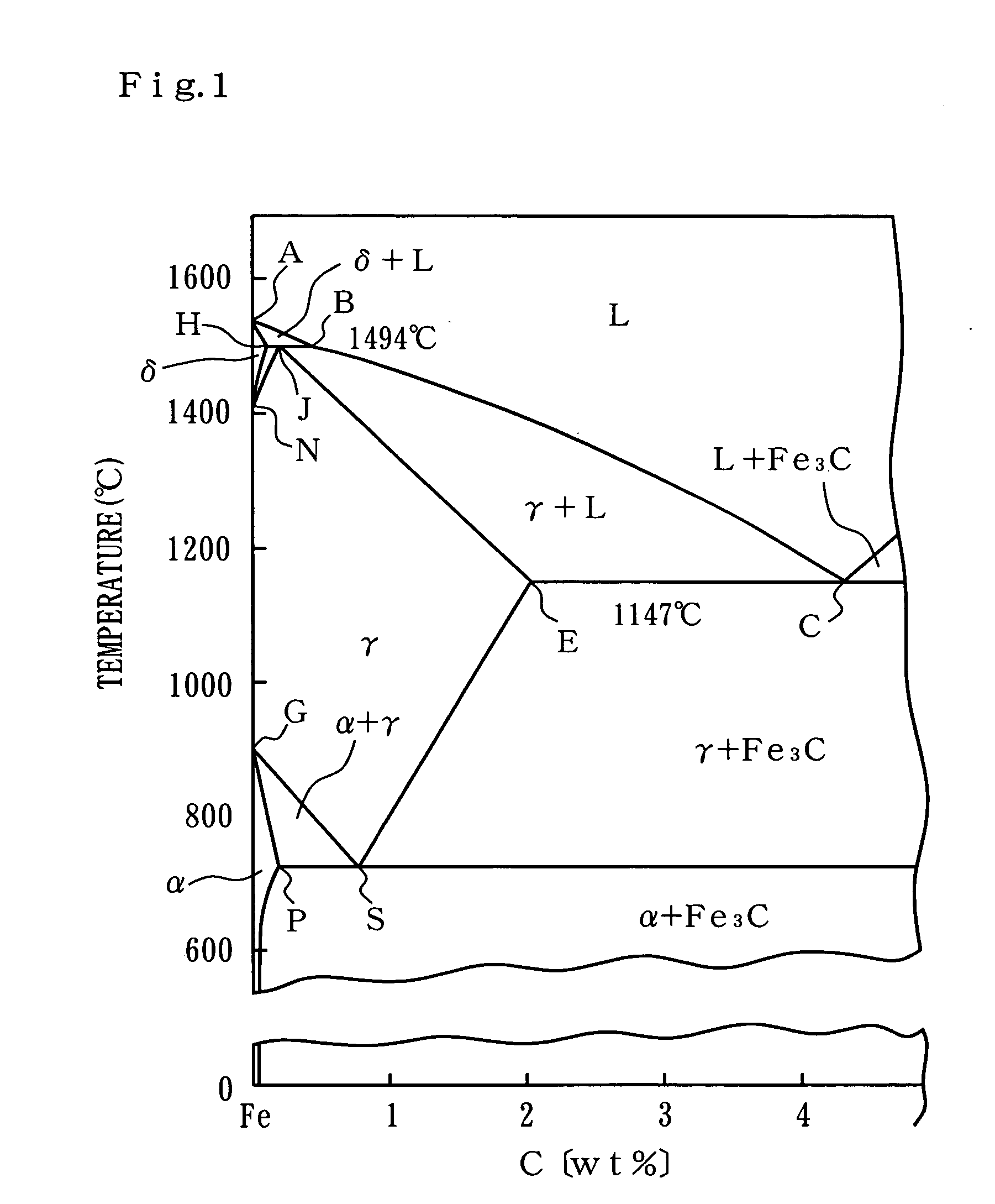
[0006] A method of gas carburizing according to an aspect of the present invention comprises the steps of predetermining limiting carburizing conditions at which the surface layer of a sample of a steel treatment object present in a carburizing atmosphere is austenitized without melting at a carburizing temperature which is not higher than a peritectic point temperature at which δ iron and liquid phase are transformed into γ iron and not less than a eutectic point temperature at which liquid phase is transformed into γ iron and cementite; and gas carburizing the treatment object under carburizing conditions which are set so as not to contradict the limiting carburizing conditions, at a carburizing temperature which is not higher than the peritectic point temperature and not less than the eutectic point temperature, wherein the limiting carburizing conditions comprise an upper limit value of a partial pressure of carburizing gas in the carburizing atmosphere at which the surface layer of the sample is austenitized without melting. Thus, the carburizing time is shortened by gas carburizing the treatment object which is austenitized by being heated to a highest possible temperature. By increasing the carburizing gas concentration in the carburizing atmosphere, the hardened layer of the treatment object can be prevented from becoming shallow and have sufficient thickness within a short time.
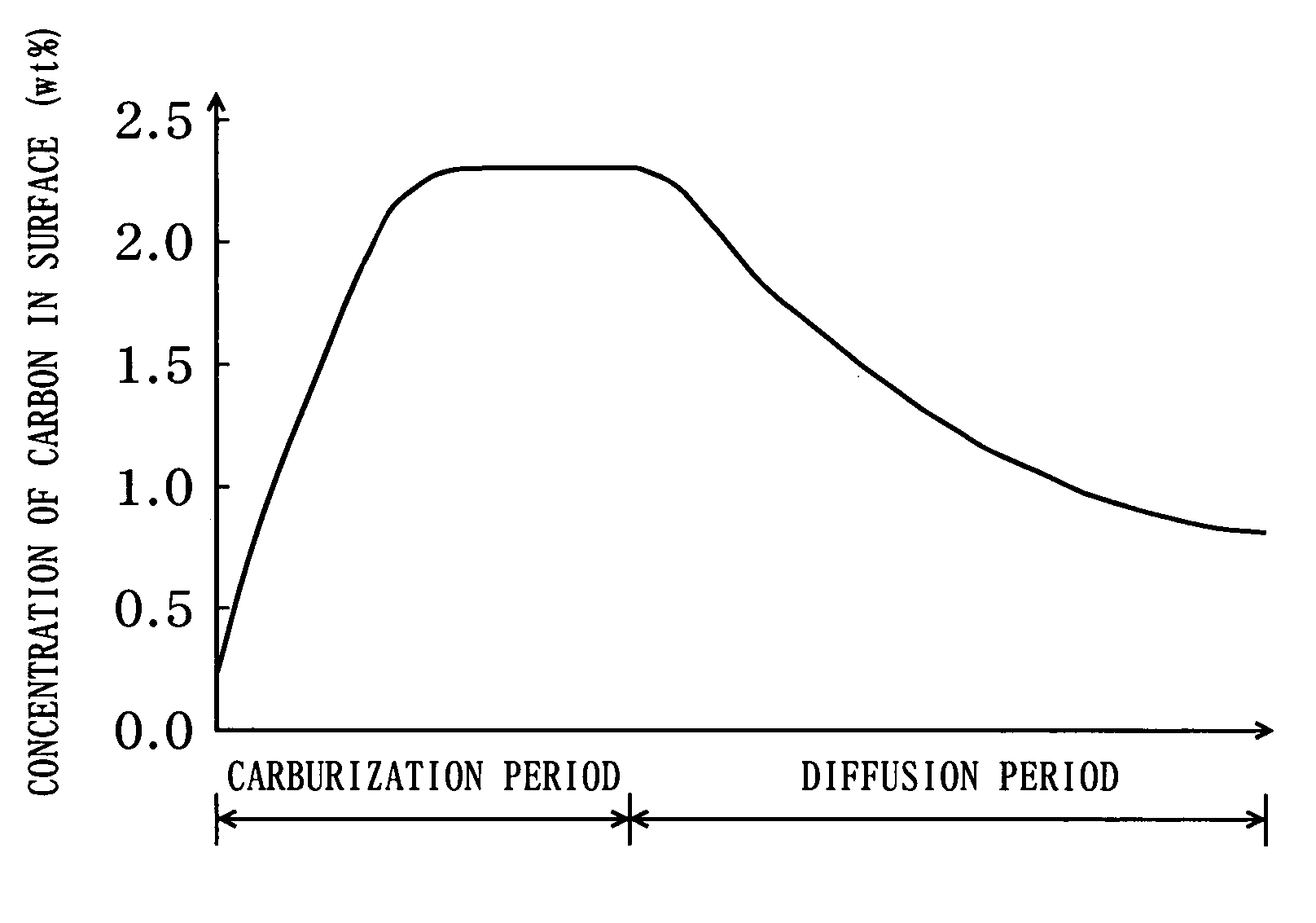
[0007] The treatment object is austenitized when heated to a temperature above the GS line or ES line in the iron-carbon equilibrium diagram shown in FIG. 1. If the concentration of carbon in the surface layer of the treatment object exceeds the JE line, melting is started in the surface layer. The present inventor has found out that an upper limit value of a partial pressure of carburizing gas at which the surface layer of the treatment object is not melted exists under given carburizing conditions such as carburizing temperature and carburizing time, and that this upper limit value decreases with the increase in carburizing temperature and increases with the decrease in carburizing time. Because the carburizing temperature range in the method of gas carburizing in accordance with the present invention is from not higher than the peritectic point temperature (1494° C.) to not less than the eutectic point temperature (1147° C.), the carburizing time can be greatly reduced. Moreover, setting the partial pressure of carburizing gas to not higher than the predetermined upper limit value makes it possible to carry out carburizing at a high temperature without causing melting in the surface layer of the treatment object. As a result, the amount of consumed energy can be greatly reduced and energy can be saved. Furthermore, the gas carburizing process can be carried out in series with other processes, for example, machining processes or different heat treatment processes.
[0008] It is preferred that the limiting carburizing conditions comprise an upper limit value of carburizing temperature and an upper limit value of carburizing time at which the surface layer of the sample is austenitized without melting, the relationship between the upper limit value of the partial pressure of carburizing gas, the upper limit value of carburizing temperature, and the upper limit value of carburizing time is predetermined, and the partial pressure of carburizing gas, carburizing temperature, and carburizing time are set such that the carburizing conditions of the treatment object do not contradict the limiting carburizing conditions which satisfy the predetermined relationship. The upper limit value of the partial pressure of carburizing gas, the upper limit value of carburizing temperature, and the upper limit value of carburizing time serving as the limiting carburizing conditions are interrelated and one of the upper limit values can be found by fixing the other two conditions among the partial pressure of carburizing gas, carburizing temperature, and carburizing time. As a result, the conditions providing for the fastest possible carburization can be easily set within a range in which the surface layer of the treatment object is not melted.

Problems solved by technology

However, if the carburizing temperature becomes too high, the treatment object melts down.
However, when the carburizing temperature is limited to a temperature less than the eutectic point temperature, the diffusion rate of carbon atoms in the treatment object is restricted.
Therefore, the carburizing time cannot be shortened significantly.
Thus, the problem is that the diffusion treatment requires a long time, thereby reducing productivity.

Method used


Image

  • Method of gas carburizing
  • Method of gas carburizing
  • Method of gas carburizing

Examples


example 1

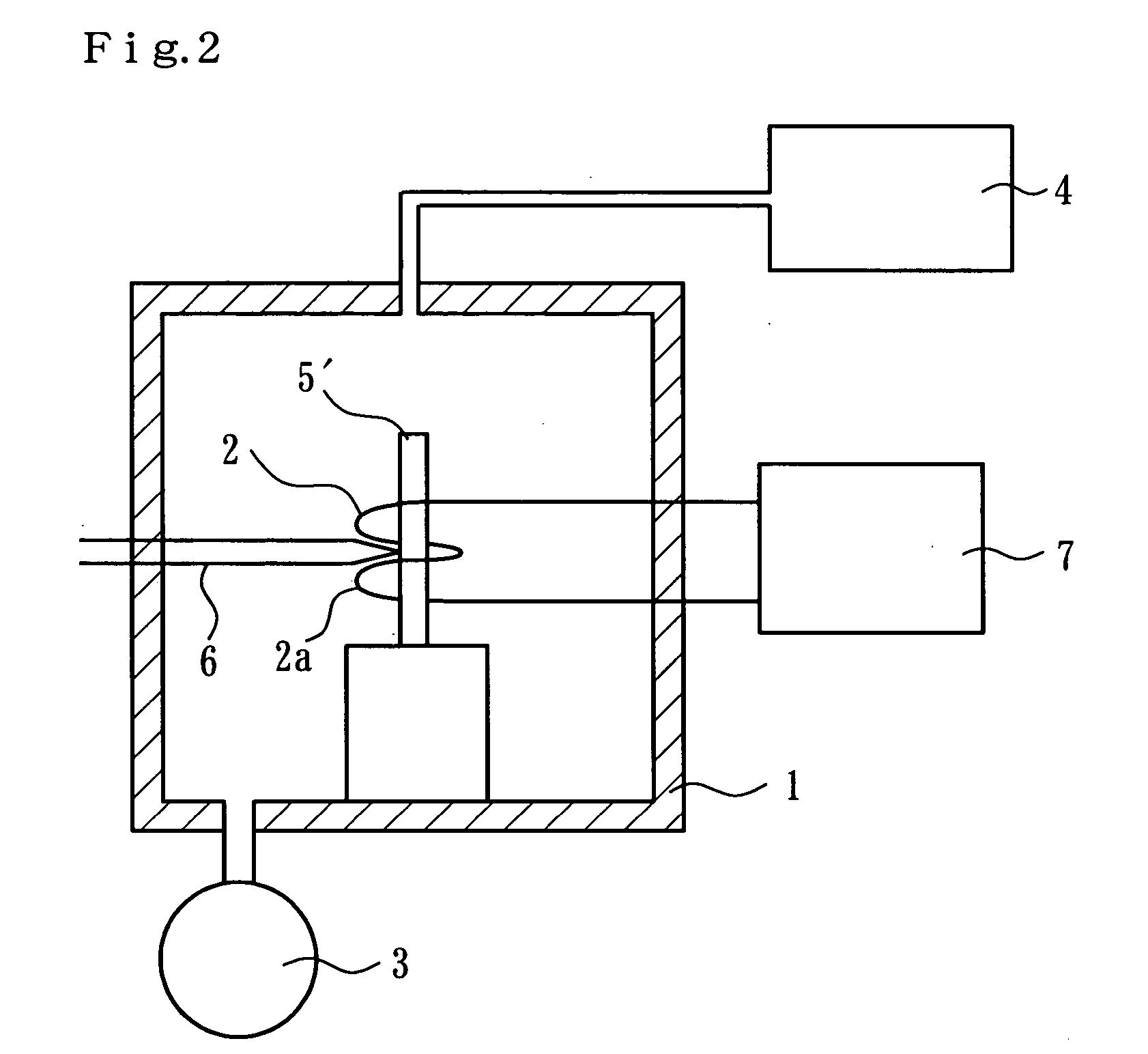
[0044] With the method of gas carburizing of the above-described embodiment according to the present invention, the limiting carburizing conditions were predetermined and gas carburization was carried out under the carburizing conditions that are set so as not to contradict the limiting carburizing conditions. The treatment object 5 had a shape of right cylinder with a diameter of 10 mm and a length of 52 mm made of a nickel-chromium-molybdenum steel (Japanese Industrial Standard SNCM420). In the present example, the carburized treatment object 5 was naturally cooled inside the vacuum container 1, hardened, polished, and finish processed with a diamond paste with a particle size of 3 micrometers, followed by hardness measurements and structure observations. The vacuum container 1 was purged prior to the carburization. The carburizing gas was methane and the dilute gas was nitrogen. During carburization, the gas for carburizing atmosphere was caused to flow inside the vacuum containe...

example 2

[0051] Gas carburization was carried out under the carburizing conditions that were set by the gas carburization method of the above-described embodiment of the present invention. The treatment object 5 had a shape of right cylinder with a diameter of 10 mm and a length of 52 mm made of a nickel-chromium-molybdenum steel (Japanese Industrial Standard SNCM420) as used in the above-described embodiment. The carburized treatment object 5 was naturally cooled inside the vacuum container 1, without being subjected to diffusion treatment, then was hardened, polished, and finish processed with a diamond paste with a particle size of 3 micrometers. The vacuum container 1 was purged prior to the carburization. The carburizing gas was methane and the dilute gas was nitrogen. Hardening was carried out by holding the treatment object 5 for 10 min inside a quartz tube furnace kept at a temperature of 860° C. in which nitrogen gas atmosphere was flowed and then quenched into oil. It goes without ...


PUM

PropertyMeasurementUnit
Temperatureaaaaaaaaaa
Partial pressureaaaaaaaaaa

Abstract

A method of gas carburizing is carried out at a carburizing temperature which is not higher than a peritectic point temperature at which δ iron and liquid phase are transformed into γ iron and not less than a eutectic point temperature at which liquid phase is transformed into γ iron and cementite. The method comprises the step of predetermining the limiting carburizing conditions at which the surface layer of a sample of a steel treatment object present in a carburizing atmosphere is austenitized without melting and the step of gas carburizing the treatment object under carburizing conditions which are set so as not to contradict the limiting carburizing conditions, at a carburizing temperature which is not higher than the peritectic point temperature and not less than the eutectic point temperature. The limiting carburizing conditions comprise an upper limit value of a partial pressure of carburizing gas at which the surface layer of the sample is austenitized without melting.

Description

TECHNICAL FIELD [0001] The present invention relates to a method for gas carburizing steel parts used, for example, in the automobile industry or machine industry. BACKGROUND ART [0002] When gas carburizing of steel treatment objects is carried out, the carburizing treatment time can be shortened by raising the carburizing temperature. However, if the carburizing temperature becomes too high, the treatment object melts down. For this reason, the carburizing temperature that has been conventionally used in practice was less than the eutectic point temperature (in the case of an iron-carbon equilibrium diagram shown in FIG. 1, it is the C point temperature which is 1147° C.) at which the liquid phase is transformed into γ iron and cementite, and usually was not higher than 1050° C. [0003] In order to shorten the carburizing treatment time at the conventional carburizing temperature, the carburizing treatment was carried out till the concentration of carbon in the surface layer of the ...

Claims


Application Information

Patent Timeline
IPC IPC(8): C23C8/22
CPCC23C8/22
Inventor TACHISATO, SHOWA
Owner KOYO THERMO SYST CO LTD
Learn More