Method of controlling hole shape during ultrafast laser machining by manipulating beam polarization

a laser machining and ultrafast technology, applied in the field of controlling the shape of the hole during ultrafast laser machining, can solve the problems of difficult to meet the positioning repeatability requirements of conventional laser micromachining methods, the portion of the center of the line being machined more, and the difficulty of manufacturing these materials, etc., to achieve the effect of constant machining capacity and similar shap

Inactive Publication Date: 2005-09-22
PANASONIC CORP
View PDF18 Cites 24 Cited by
  • Summary
  • Abstract
  • Description
  • Claims
  • Application Information

AI Technical Summary

Benefits of technology

[0015] An exemplary embodiment of the present invention is a method for controlling the shape of the area laser machined by a pulse of laser light on a surface of a workpiece, such that the controlled shape has a desired elliptical shape with its major axis aligned in a desired direction and the length of this major axis is less than or equal to a diameter of a beam spot of the pulse of laser light. The pulse of laser light is generated and focused to the beam spot within a target area of the microstructure workpiece. The polarization of the pulse of laser light is adjusted such that, in the beam spot, the pulse of laser light is...

Problems solved by technology

The feature sizes used to form photonic crystals and the precise alignment requirements of these features complicate manufacture of these materials.
This method requires precise and repeatable positioning control (<10 nm in some cases) and may lead to portions of the center of the line being machined more than the corresponding edge portions.
Traditionally, such positioning repeatability requirements have been difficult to meet with conventional laser micro...

Method used


Image

  • Method of controlling hole shape during ultrafast laser machining by manipulating beam polarization
  • Method of controlling hole shape during ultrafast laser machining by manipulating beam polarization
  • Method of controlling hole shape during ultrafast laser machining by manipulating beam polarization

Examples


Embodiment Construction

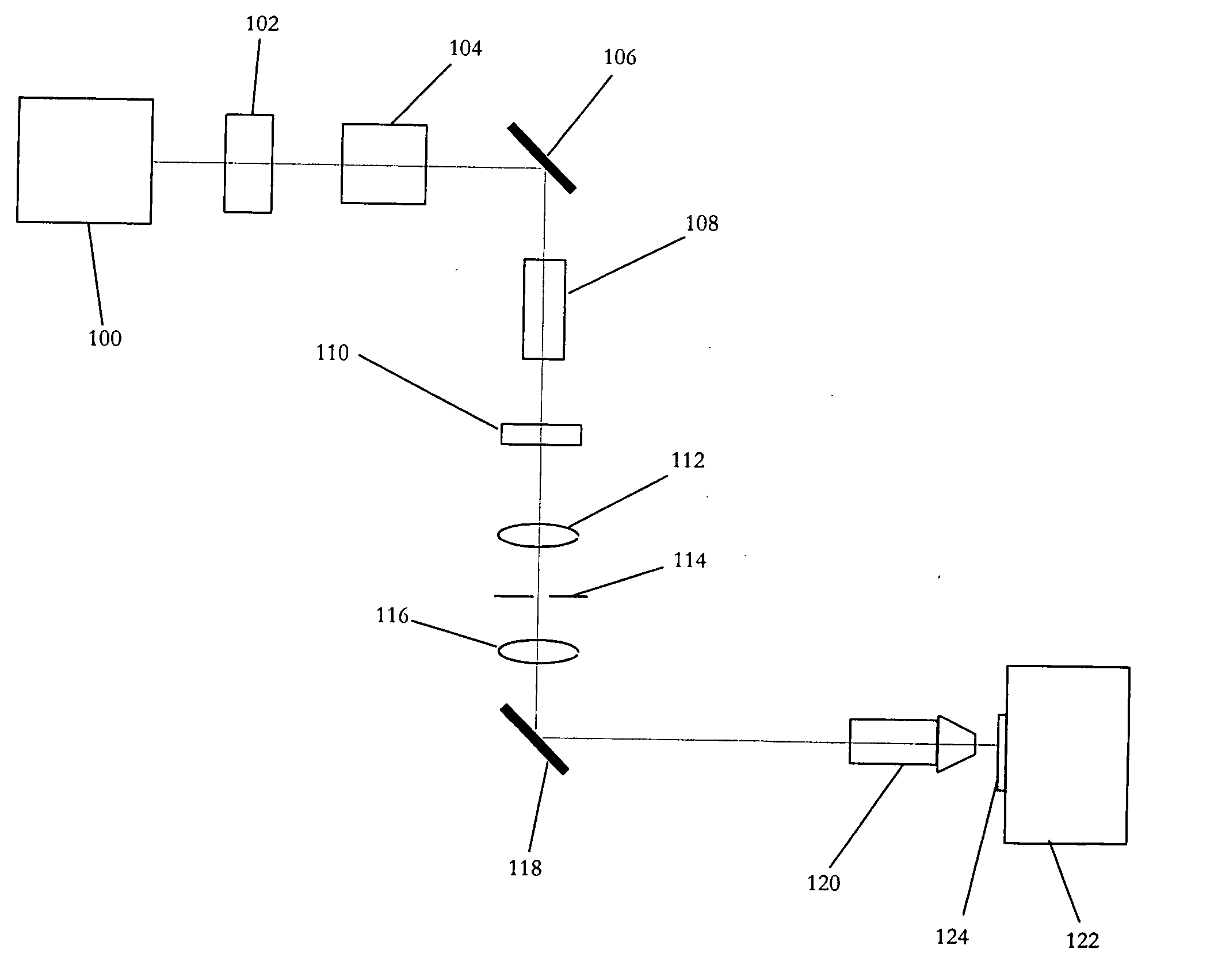
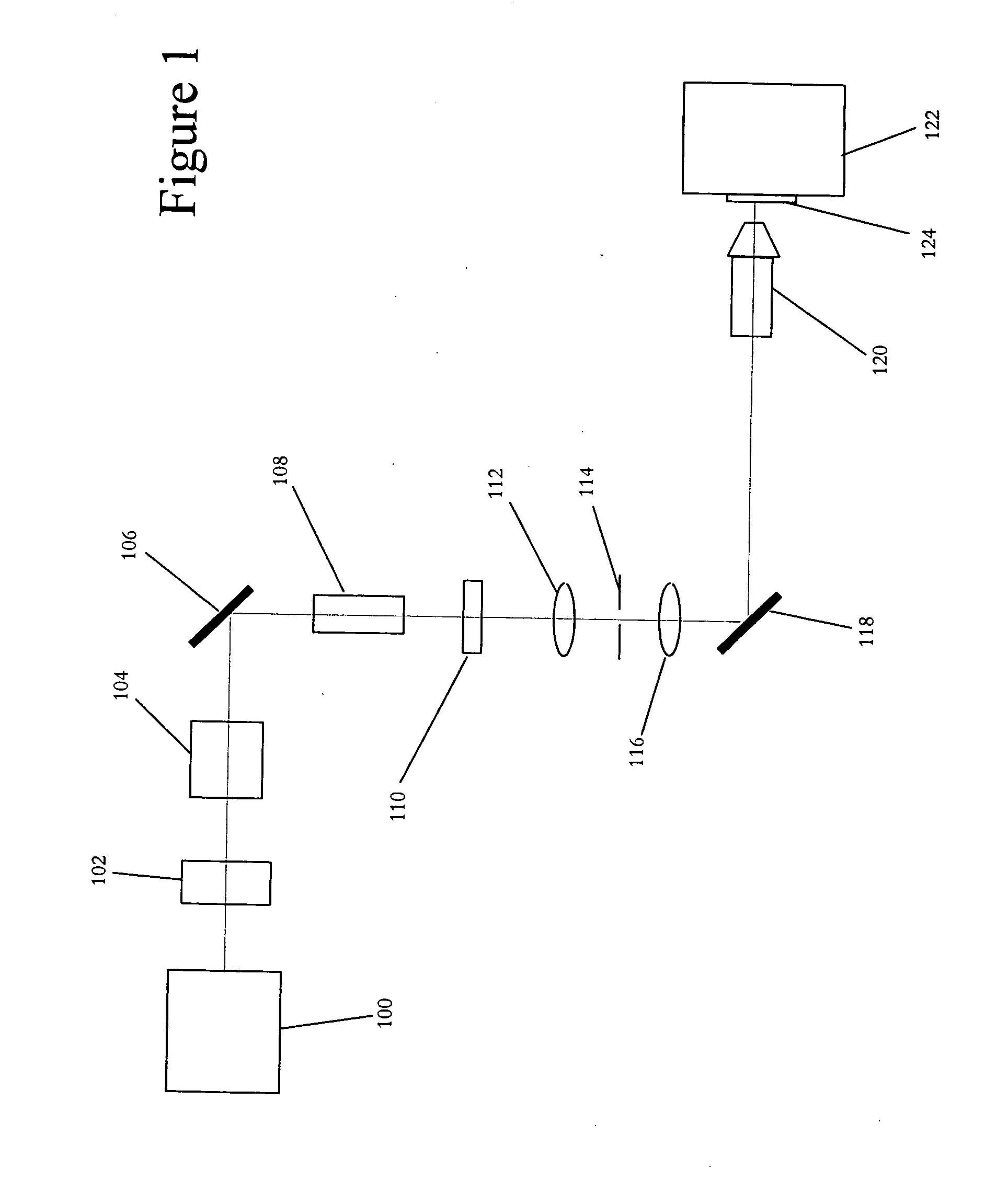
[0032]FIG. 1 illustrates a simplified block diagram of an exemplary laser micro-machining system according to the present invention. This exemplary system includes: ultrafast laser source 100; shutter 102; variable attenuator 104; dichroic mirrors 106 and 118; linear polarization rotator 108; rotatable quarter wave plate 110; lenses 112, 116, and 120; mask 114; and workpiece holder 122. The optical beam path of the exemplary micro-machining laser system is shown as a dotted line.

[0033] In this exemplary system, ultrafast laser source 100 may desirably include any type of gain medium typically used for ultrafast laser machining applications, such as: a solid state gain material, laser dye gain material, and / or gaseous gain material, including excimer gases. Harmonic generating crystals and / or amplifiers may be used within this component. Ultrafast laser source 100 desirably produces nearly Fourier-transform limited pulses having a duration of less than about 1 ns, typically less tha...


PUM

PropertyMeasurementUnit
Nanoscale particle sizeaaaaaaaaaa
Poweraaaaaaaaaa
Compositionaaaaaaaaaa

Abstract

A method for controlling the shape of the area machined by a pulse of laser light on a surface, such that the shape has a desired elliptical shape with its major axis aligned in a desired direction and the length of this major axis is less than or equal to a diameter of a beam spot. The pulse is generated and focused to the beam spot within a target area. The polarization of the pulse is adjusted to be elliptically polarized with an axis of the polarization ellipse oriented in the desired direction. The ellipticity of the polarization of the pulse is adjusted such that the pulse of laser light has contours of constant machining capacity on the workpiece surface, which have a similar shape to the desired shape. The fluence of the pulse light is controlled such that the area machined by the pulse is substantially the desired shape.

Description

FIELD OF THE INVENTION [0001] The present invention concerns a method for micro- and nano-machining of features of various shapes using ultrafast laser pulses. This method may also allow the laser machining of expanded beam mode and elliptical mode shifting waveguide structures. BACKGROUND OF THE INVENTION [0002] As products get smaller and smaller, there is greater demand for micro-electrical-mechanical systems (MEMS), micro-optical devices and photonic crystals. With this demand, there is an associated increased interest in micro- and nano-machining. There are numerous possible applications for MEMS. As a breakthrough technology, allowing unparalleled synergy between previously unrelated fields such as biology and microelectronics, many new MEMS applications have emerged and many more may emerge in the near future, expanding beyond those currently identified or known. Additional applications in quantum electric devices, micro-optical devices and photonic crystals are also emerging...

Claims


Application Information

Patent Timeline
IPC IPC(8): B23K26/073B81C99/00
CPCB23K26/0736B82Y30/00B82Y10/00
Inventor LI, MING
Owner PANASONIC CORP
Why Eureka
Try Eureka