Heating element control

a technology of heating element and control circuit, which is applied in the direction of high frequency current welding apparatus, engine ignition, electron beam welding apparatus, etc., can solve the problems of large temperature errors, difficult to achieve effective thermal coupling between the sensor and the heating element, and the possibility of subsequently measuring the temperature of the heating elemen

Active Publication Date: 2005-09-22
INTEGRATED ELECTRONICS SOLUTIONS
View PDF21 Cites 32 Cited by
  • Summary
  • Abstract
  • Description
  • Claims
  • Application Information

AI Technical Summary

Benefits of technology

[0010] An object of the invention is to provide an alternative circuit arrangement which minimises these disadvantages of known circuits for controlling the...

Problems solved by technology

Effective thermal coupling between the sensor and the heating element is difficult to achieve in high temperature applications and improper thermal coupling results in large temperature errors.
When this occurs it is not possible to subsequently measure the temperature of the heating element.
Investigations have shown that this circuit has a number of limitations.
In certain applications where the PTC...

Method used


Image

  • Heating element control
  • Heating element control
  • Heating element control

Examples


Embodiment Construction

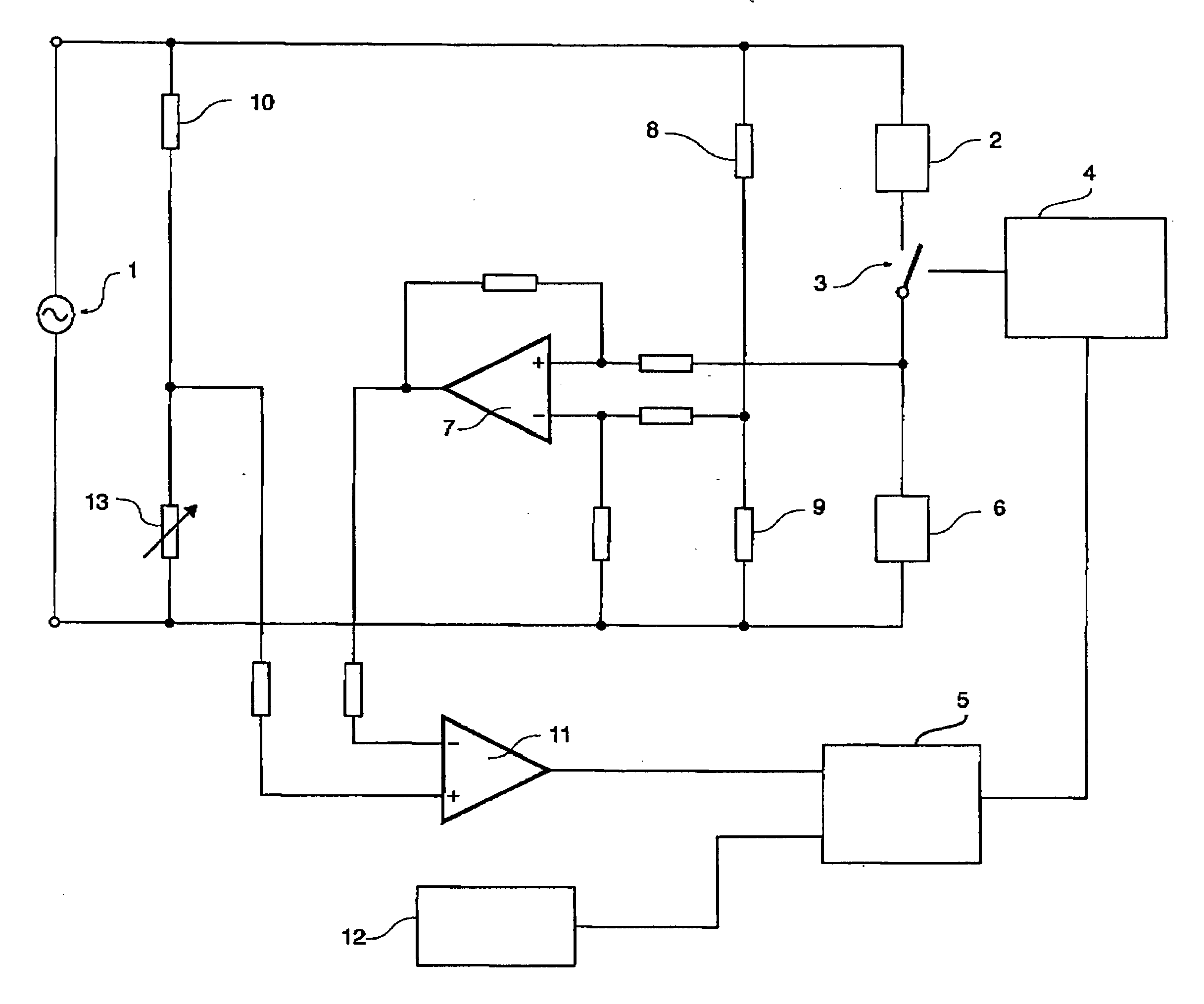
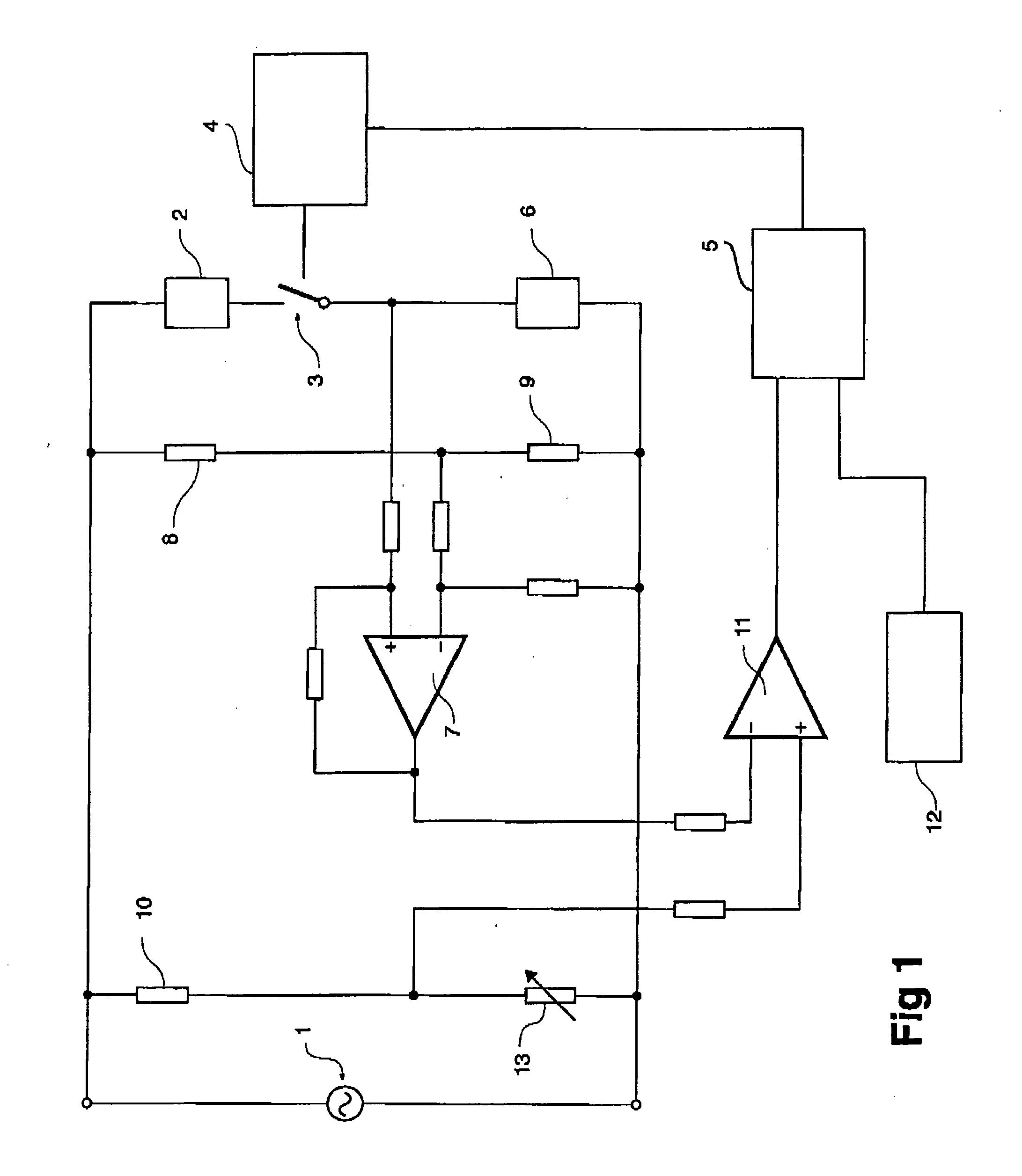
[0050] Referring to the drawings in detail, FIG. 1 shows a simplified circuit diagram of the invention. A mains voltage supply 1 energises a heating element 2 when a switch 3 is closed. The heating element has a non-zero temperature co-efficient of resistance. The switch is operated by switch controller 4, in response to signals from logic circuitry 5.

[0051] Current sensor 6 provides a signal to difference 7 amplifier, which acts as a difference sensor. Resistors 8 and 9 form a zero set point controller. The resistors are selected so that the output of the difference amplifier is essentially zero when the heating element temperature is at its minimum operational value. This voltage divider formed by resistors 8 and 9 provides another input to the difference amplifier 7. Thus the output of the difference amplifier is an alternating voltage, whose magnitude is proportional to the change in output voltage of the current sensor due to changes in the resistance of the heating element.

[...


PUM

PropertyMeasurementUnit
Temperatureaaaaaaaaaa
Electrical resistanceaaaaaaaaaa
Threshold limitaaaaaaaaaa

Abstract

A controller adapted to control the temperature of a heating elements with a wide range of positive temperature coefficient of resistance, including very low values, using a sensor in line with the heating element. The controller is able to take account of non-constant mains power supplies and variation in the element resistance over time.

Description

TECHNICAL FIELD [0001] The present invention relates to a circuit arrangement for controlling the temperature of a heating element supplied from an AC mains supply, particularly being of a type where the resistance of the element is used as a measure of its temperature. [0002] 2. Background Art [0003] It is known to use time proportional control for on / off triac circuit arrangements for controlling the temperature of heating elements in hotplates, frypans, irons and the like. In these circuit arrangements the temperature of the element is sensed by a separate negative temperature coefficient (NTC) or separate positive temperature coefficient (PTC) thermistor thermally coupled to the object to be controlled. Effective thermal coupling between the sensor and the heating element is difficult to achieve in high temperature applications and improper thermal coupling results in large temperature errors. Alternative methods of sensing the temperature of the element rely on using the temper...

Claims


Application Information

Patent Timeline
IPC IPC(8): G05D23/20H05B1/02
CPCF02P19/022H05B1/0288G05D23/2006F02P19/025G05D23/1906G05D23/20
Inventor CRAWFORD, JOHNPOTTER, MARKALTSCHWAGER, KEVIN
Owner INTEGRATED ELECTRONICS SOLUTIONS
Why Eureka
Try Eureka