
Optical pickup

a technology of optical pickups and optical beams, applied in the field of optical pickups, can solve the problems of difficult beam formation in two wavelengths simultaneously in the same prism, complex structure and functions of the optical pickup used for this, and achieve the effect of satisfactory heat release and simple structur

Inactive Publication Date: 2005-09-22
JVC KENWOOD CORP A CORP OF JAPAN
View PDF4 Cites 11 Cited by
  • Summary
  • Abstract
  • Description
  • Claims
  • Application Information

AI Technical Summary

Benefits of technology

[0042] An object of the present invention is to provide an optical pickup that can replay using a plurality of wavelengths and can record using at least one of the wavelengths, that is compact and of a simple structure and that realizes satisfactory release of heat from the light source of the wavelength used for recording.
[0044] Satisfactory release of heat of the primary laser light source is achieved and a simple structure of the optical pickup is realized by integration of the secondary laser light source with the light receiving elements. Further, the optical axes of the primary and secondary laser lights are perfectly on the same axis in respect of the laser light optical path separating elements.
[0061] This optical pickup device realizes adequate heat release of heat generated by the primary laser light source and has a simple structure as the secondary laser light source is integrated with the light receiving elements. Further, the optical axes of the primary and secondary laser lights are perfectly on the same axis in respect of the laser light optical path separating elements. Moreover, either of the primary laser light or the secondary laser light can be used for recording to an information recording medium. The primary laser light is structured having an optical system dependent on polarization, thereby realizing improved return path efficiency and the secondary laser light is structured having an optical system independent of polarization, such that good playout properties are maintained even in respect of a medium having substantial birefringence.

Problems solved by technology

Further, compatibility in both recording and reproduction is needed for all of the various standards used for DVD, however the structure and functions of an optical pickup used for this are complex.
The need for such devices to be inexpensive, small and lightweight are increasing due to the demands of the general population, thus development of a simple, compact and inexpensive optical pickup, that is nonetheless complex and replete with multiple functions, is required.
Limitations applying to beam formation include 1) it must be performed in parallel light beams and 2) beam formation in two wavelengths simultaneously in the same prism is difficult due to chromatic aberration.
In the case of CD systems the above described load on the laser source is light and such beam formation is unnecessary.
However, this pickup has separate respective collimator systems for the outward path and return path at the DVD side for example and as there are basically no common parts of the CD side and DVD side, the structure becomes complex as a large number of parts are required notwithstanding the integrated device.
Accordingly, the optical axis of emitted light and the optical axis of received light are disposed mutually separated at approximately 90 degrees such that concentration of the light receiving parts is not practically possible.
Moreover, the two wavelengths of the CD laser light and the DVD laser light are optical systems dependent on polarization, accordingly there is concern of deterioration in the replay performance of a CD disk having substantial birefringence.
The object of this optical pickup also is the utilization of integrated device, however two integrated devices are required and the same problem of requiring a complex structure persists.
Further, this optical pickup is for reproduction and does not provide an optical system that more efficiently utilizes optical properties such as by beam formation and a polarized light system, thus even if high output laser is used this structure does not actually enable recording to an optical disk.
Further, two integrated devices are necessary as a result of the progression towards integration and this leads unavoidably to complexities in structure and increased production costs.
When integration and miniaturization are pursued overall in a recording type optical pickup device in the case of a conventional optical pickup as described above, the following problems occur due to the requirements of a system accommodating each of the different wavelengths as described above.
In the above described optical system dependent on polarization, efficiency is achieved in what is largely an ideal outward and return path by use of a polarized light beam splitter, but in the case of a CD system which is a polarization independent optical system such efficiency cannot be realized.
Accordingly substantial power is consumed and a concomitant rise in temperature due to heat generation is unavoidable when recording is performed, in other words, when the laser is generating light at high output.
In contrast to this however, in an integrated device in which the light receiving elements or hologram elements are integrated, a plurality of parts intercede in the path of heat conduction thereby preventing sufficient heat release.
Realizing both a simple structure and adequate heat release is difficult especially when two wavelengths share common optical paths and where integrated devices are used for both wavelengths.

Method used


Image

  • Optical pickup
  • Optical pickup
  • Optical pickup

Examples


first embodiment

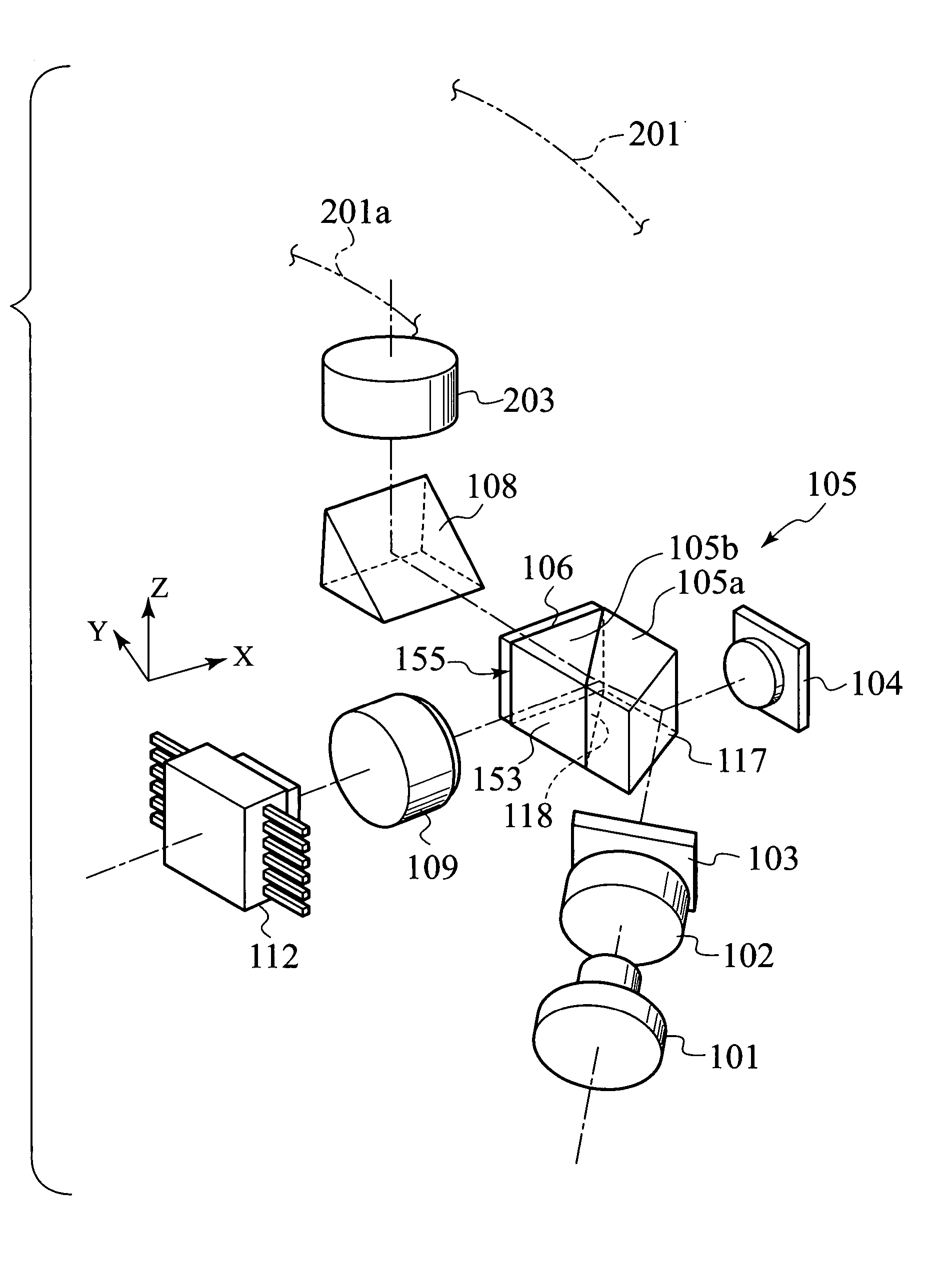
[0111]FIG. 6 and FIG. 7 are schematic illustrations of an optical pickup according to the present invention.

[0112] As shown in FIG. 6 and FIG. 7 the optical pickup 100 according to this first embodiment comprises a primary laser light source 101 for emitting a primary laser light having a first wavelength and that is of sufficient power for recording, an integrated device 112 further comprising a secondary laser light source emitting a secondary laser light having a second wavelength that is longer than the first wavelength and that is of sufficient power for recording as well as light receiving means for receiving light from the primary and the secondary laser lights, and a polarized light beam splitter 105 further comprising an inclined surface 117 having light polarization selectivity in respect of the first laser light having the first wavelength, no light polarization selectivity in respect of the second laser light having the second wavelength and that is injected with the pri...

second embodiment

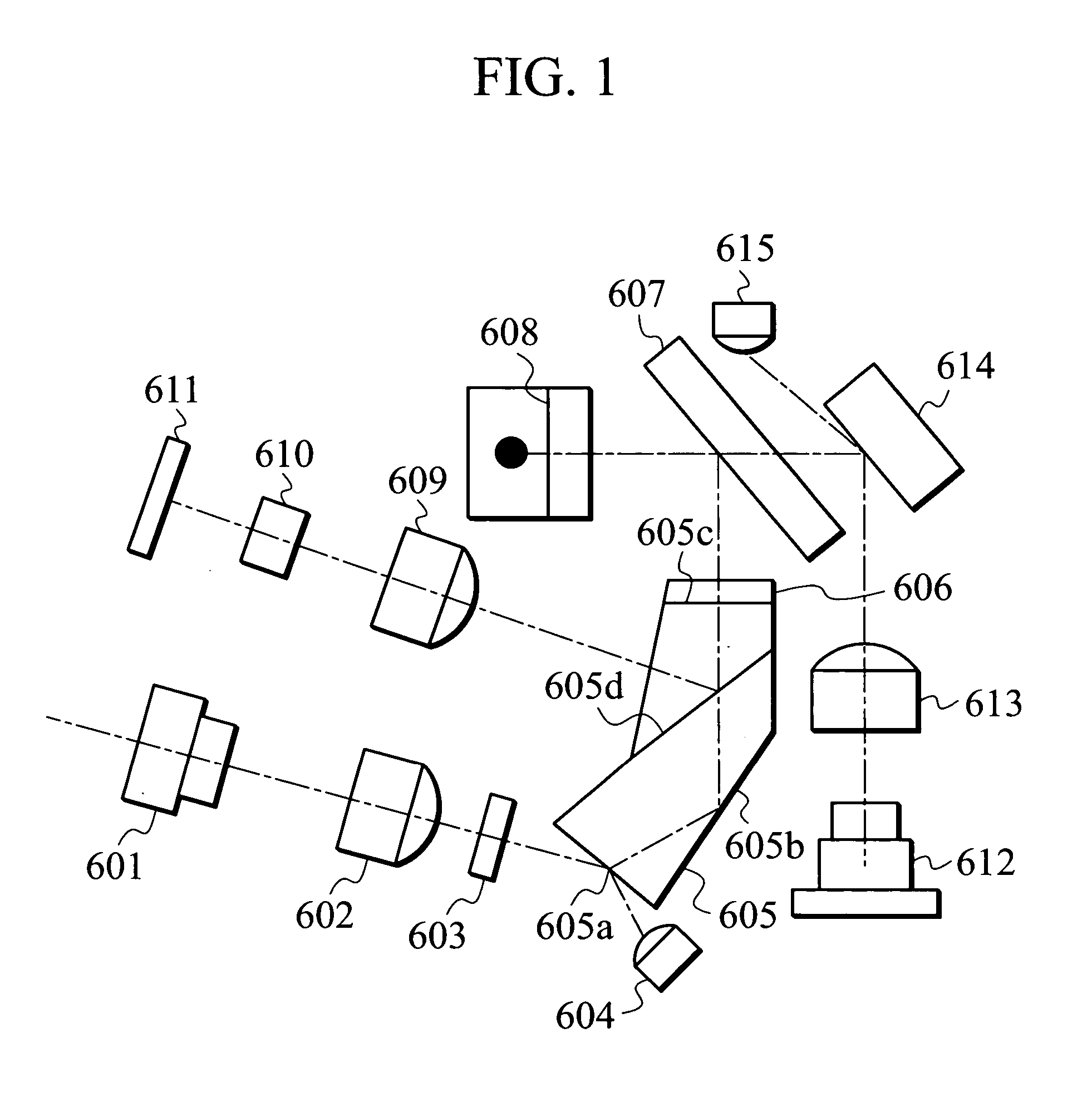
[0216]FIG. 17 shows a schematic illustration of an optical pickup according to the present intention.

[0217] In FIGS. 6 to 12 those elements having like reference numerals indicate those elements that are similar or the same as the respective elements of the first embodiment.

[0218] The optical pickup 240 of this second embodiment is of substantially the same configuration as the optical pickup according to the first embodiment.

[0219] That is to say, as shown in FIG. 17, this optical pickup comprises a primary laser light source 241 for emitting a primary laser light (wavelength of the 650 nm band) having sufficient power for recording, a polarized light beam splitter 244 including a polarized light beam splitting (PBS) film surface 118, and an integrated device 112 further comprising a secondary light source 128 (FIG. 11) for emitting a secondary laser light (having a wavelength of the 780 nm band) and having sufficient power for recording as well as light receiving means for recei...

third embodiment

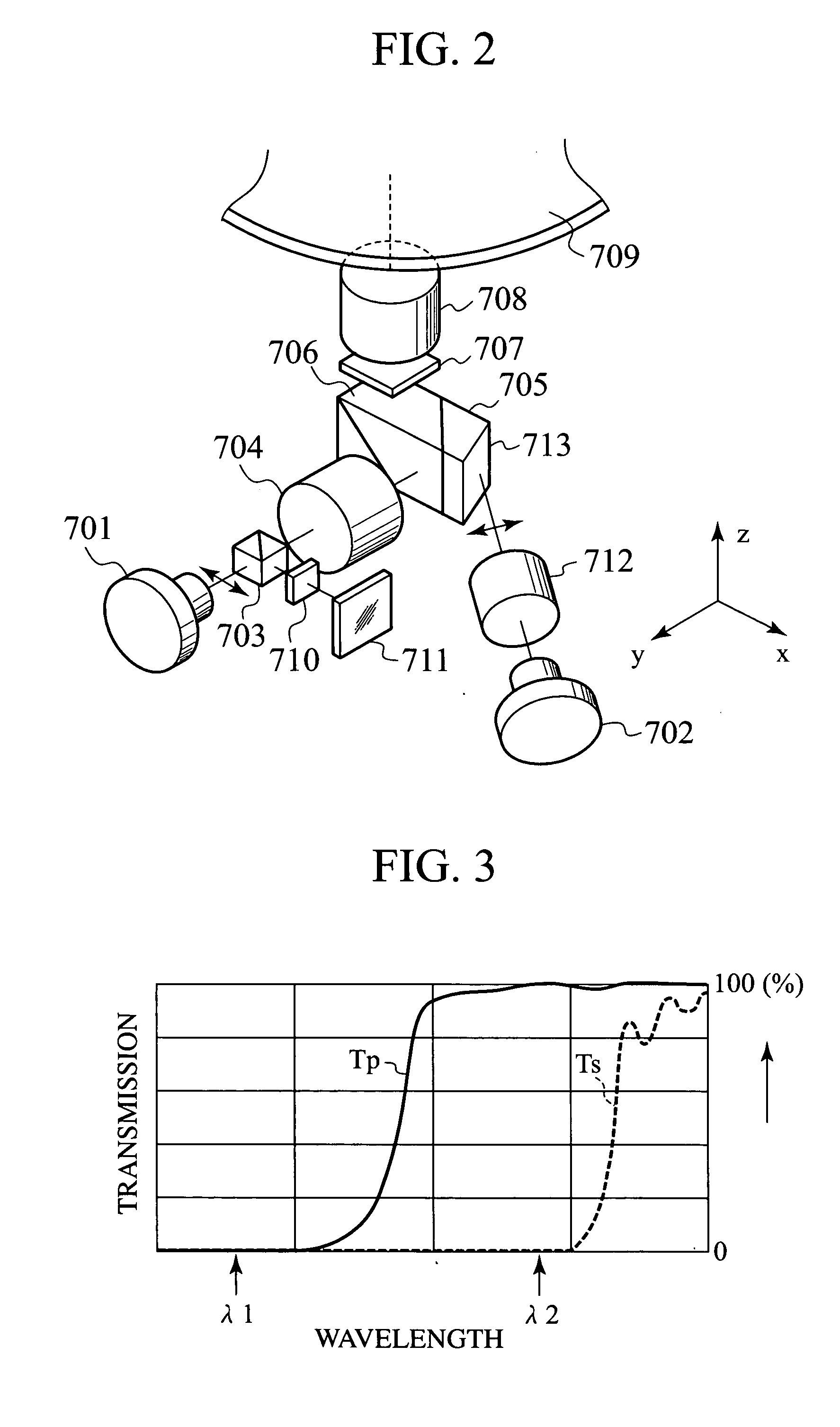
[0225]FIG. 18 shows a schematic illustration of an optical pickup according to the present invention.

[0226] Like reference numerals are applied for elements of this third embodiment that are the same as those of the first and second embodiments and a description of those elements is omitted.

[0227] The points of similarity between the optical pickup 300 of this third embodiment and the optical pickup of the second embodiment are as follows. [0228] (1) The polarized light beam splitter 344 having a PBS film surface 318 is of a cubic form. [0229] (2) The collimator lens 245 is disposed between the polarized light beam splitter 344 having the PBS film surface 318 and the mirror 108 so that the collimator lens 245 can be used for both the primary and secondary laser lights.

[0230] On the other hand, the points of difference between the optical pickup 300 of this third embodiment and the optical pickup of the second embodiment are as follows. [0231] (1) The PBS film surface 118 has the w...


PUM

PropertyMeasurementUnit
wavelengthaaaaaaaaaa
thicknessaaaaaaaaaa

Abstract

An optical pickup having a simple structure and that is capable of recording using a plurality of wavelengths is provided, comprising a primary laser light source for emitting a primary laser light having a first wavelength and that is of sufficient power for recording, an integrated device further comprising a secondary laser light source for emitting a secondary laser light having a second wavelength that is longer than the first wavelength and that is of sufficient power for recording as well as light receiving elements for receiving the light of the primary and secondary laser lights, and a polarized light beam splitter having polarization selectivity in respect of the secondary laser light.

Description

FIELD OF THE INVENTION [0001] The present invention relates to an optical pickup used for recording or reproducing optical information recorded to a medium such as an optical disk or the like. BACKGROUND OF THE INVENTION [0002] DVD's (Digital Versatile Disc) that have approximately seven times the capacity of CD's (Compact Disc) have rapidly gained in popularity in recent years. Further, DVD-videos that are capable of being reproduced in high-volume are replacing VHS and the like, tape mediums used as mediums for renting and distribution of contents of movies and other material. [0003] Moreover, standards for recording such as DVD-RAM, DVD-R, DVD-RW, DVD+R and DVD+RW are becoming commonplace for PC drives and video recorder units. [0004] Recordable CD-R is already commonly used. [0005] In light of the above, recording functions for either the 650 nm band for DVD or the 780 nm band for CD are required in an optical disk recording device. [0006] Further, compatibility in both recordin...

Claims


Application Information

Patent Timeline
Patent Type & Authority Applications(United States)
IPC IPC(8): G11B7/00G11B7/09G11B7/125G11B7/135
CPCG11B7/0916G11B2007/0006G11B7/1356G11B7/1275G11B7/1395
Inventor OHYAMA, MINORU
Owner JVC KENWOOD CORP A CORP OF JAPAN
Learn More