Base dosing water purification system and method

Inactive Publication Date: 2005-09-29
TAIWAN SEMICON MFG CO LTD
5 Cites 14 Cited by

AI-Extracted Technical Summary

Problems solved by technology

This generates silicon particles which are washed away with rinse water used to rinse particles away from the die, causing the formation of wastewater.
The treatment of wastewater is a complex process, due in part to the constantly-changing nature of the concentration and identities of the contaminant particles to be treated.
Industrial wastewaters produced during industrial processing, such as electroplating, printed circuit manufacturing and machining, have proven difficult to treat due to the many different types of contaminants present in the wastewater.
These ions are known as mobile ionic contaminants (MICs), which create performance problems in semiconductor devices.
Organic materials are another source of contaminant which adversely affect the ability to grow oxide films on wafers.
In addition, bacteria in the water shed f...

Benefits of technology

[0024] In accordance with these and other objects and advantages, the present invention generally relates to a new and improved water purification system including a high-efficiency reverse osmosis (HERO) system and a base dosing system for rapidly raising the pH of wastewater treated in the system. The invention includes an ion exchange unit for initially removing positive and negative i...

Abstract

An improved water purification system including a high-efficiency reverse osmosis (HERO) system and a base dosing system for rapidly raising the pH of wastewater treated in the system. The invention includes an ion exchange unit for initially removing positive and negative ions from the wastewater. A high-efficiency reverse osmosis (HERO) system is provided downstream of the ion exchange unit for further removing ions from the wastewater. A base dosing system is provided between the ion exchange unit and the HERO system for dosing a base into and rapidly raising the pH of the wastewater as the wastewater flows from the ion exchange unit into the HERO system.

Application Domain

Reverse osmosisWater/sewage treatment by neutralisation +13

Technology Topic

Ion exchangeIon +3

Image

  • Base dosing water purification system and method
  • Base dosing water purification system and method

Examples

  • Experimental program(1)

Example

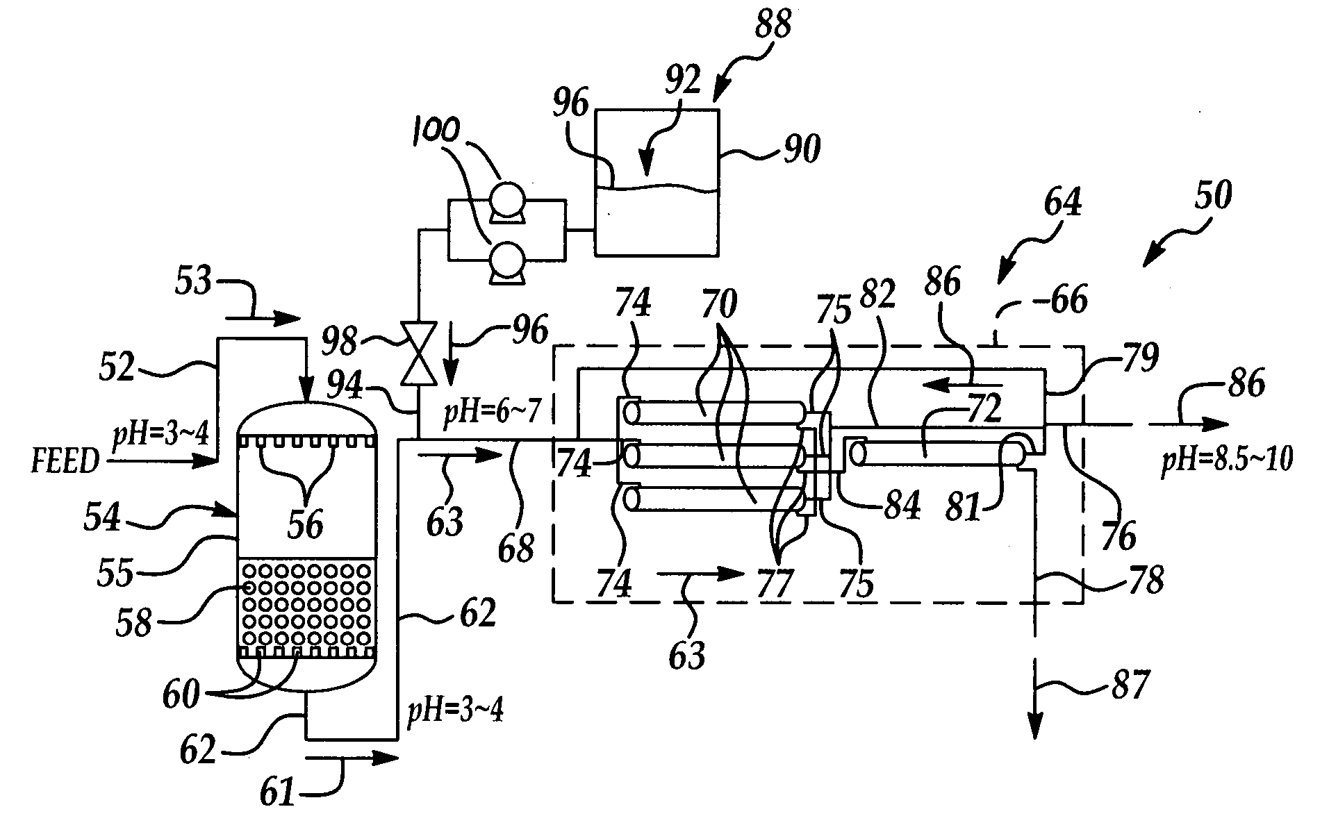
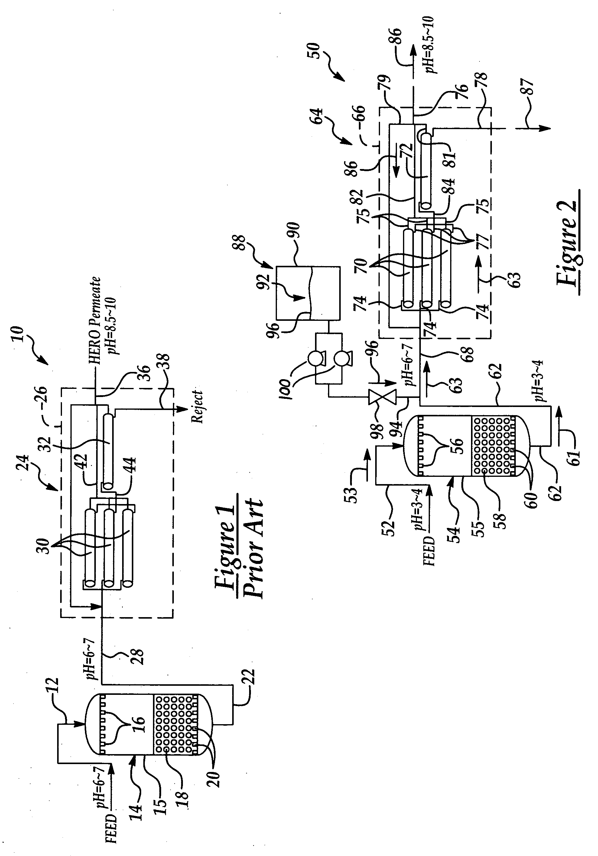
[0030] The present invention contemplates a water purification system having a base dosing system for rapidly raising the pH of acidic wastewater, typically from semiconductor fabrication processes, as the wastewater flows from an ion exchange unit to a high-efficiency reverse osmosis (HERO) system. The present invention further includes a base dosing method for raising the pH of acidic wastewater during treatment of the wastewater. The base dosing system includes a base dispensing tank that contains a sodium hydroxide solution of high concentration. The sodium hydroxide is dispensed into the wastewater as the wastewater flows from an ion exchange unit, raising the pH of the wastewater from about 3˜4 to about 6˜7 prior to entry of the wastewater into a HERO system. The HERO system further raises the pH of the wastewater to about 8.5˜10. The resulting purified, de-ionized water is suitable for use in semiconductor fabrication processes, for example. However, it is understood that the system and method of the present invention is equally applicable to purifying wastewater in other industries.
[0031] Referring to FIG. 2, wherein a water purification system having a dosing system in accordance with the present invention is generally indicated by reference numeral 50. In a typical embodiment, the system 50 includes an inlet line 52 that receives raw wastewater 53 typically from one or various semiconductor facbrication processes. For example, the wastewater 53 may include wastewater from a chemical mechanical planarization (CMP) process or a wafer-rinsing or cleaning process, for example.
[0032] The inlet line 52 is provided in fluid communication with a tank 55 of an ion exchange unit 54. Multiple inlet nozzles 56, which are provided in fluid communication with the inlet line 52, are typically provided in the upper portion of the tank 55. An ion exchange resin bed 58 is provided in the bottom portion of the tank 55 for the removal of both positive and negative ions from the wastewater 53 in a first wastewater treatment process, as hereinafter described. Multiple outlet nozzles 60 are provided in the bottom of the tank 55, at the bottom of the ion exchange resin bed 58. An ion exchange outlet line 62, which communicates with the outlet nozzles 60, extends typically from the bottom of the tank 55 to distribute the partially-treated wastewater 61 from the tank 55.
[0033] A HERO system inlet line 68 extends from the ion exchange outlet line 62 and enters a HERO (high-efficiency reverse osmosis) system 64, which will be herinafter described. A base dosing system 88 includes a base dispensing tank 90 having a tank interior 92 for containing a sodium hydroxide aqueous solution of high concentration. A dispensing conduit 94 extends from the base dispensing tank 90 and is disposed in fluid communication with the HERO system inlet line 68. A valve 98 is typically provided in the dispensing conduit 94 to control the quantity and rate of base 96 dispensed from the tank interior 92 to the HERO system inlet line 68, as hereinafter described. One or multiple pumps 100 may be provided between the base dispensing tank 90 and the dispensing conduit 94 to pump the base 96 from the base dispensing tank 90 to the dispensing conduit 94.
[0034] The HERO system 64 typically includes a housing 66 into which the HERO system inlet line 68 extends. Multiple first stage filter membranes 70 are provided in fluid communication with the HERO system inlet line 68 through respective first stage inlet lines 74. Multiple first stage permeate outlet lines 75 lead from the respective first stage filter mambranes 70 to a second stage bypass line 82 which communicates with a main permeate outlet line 76. Multiple stage transfer lines 77 extend from the respective first stage filter membranes 70 to a second stage inlet line 84, which leads into a second stage filter membrane 72. A second stage outlet line 81 and a reject outlet line 78 extend from the outlet end of the second stage filter membrane 72. A permeate feedback line 79 may extend from the main permeate outlet line 76 to the HERO system inlet line 68. A filter bypass line 80 may extend directly from the HERO system inlet line 68 to the reject outlet line 78.
[0035] In operation of the water purification system 50, raw wastewater 53 enters the tank 55 of the ion exchange unit 54 through the inlet line 52 and inlet nozzles 56, respectively. Typically, the raw wastewater 53 is distributed into the tank 55 in batches, rather than as a continuous flow. As the wastewater 53 is typically pulled by gravity through the ion exchange resin bed 58, large cations and anions, such as Ca++ and SO4−, bind to the resins in the resin bed 58 and are removed from the wastewater 53. The partially-purified wastewater 61 passes from the tank 55 through the outlet nozzles 60 and ion exchange outlet line 62, respectively.
[0036] The partially-purified wastewater 61 from the ion exchange unit 54 passes into the HERO system 64 through the HERO system inlet line 68. As the partially-treated wastewater 61 flows through the HERO system inlet line 68 toward the HERO system 64, sodium hydroxide aqueous base solution 96 is dispensed from the base-dispensing tank 90, through the dispensing conduit 94 and into the HERO system inlet line 68, typically by operation of the pump or pumps 100. In the HERO system inlet line 68, the base solution 96 mixes with the partially-treated wastewater 61 from the ion exchange unit 54, and forms neutralized or almost-neutralized wastewater 63. The wastewater 63 flows into the HERO system 64 through the HERO system inlet line 68.
[0037] Some of the wastewater 63 flows from the HERO system inlet line 68, into the first stage filter membranes 70 through the respective first stage inlet lines 74; from the first stage filter membranes 70, through the respective first stage permeate outlet lines 75 and into the second stage bypass line 82; and from the second stage bypass line 82 into the main permeate outlet line 76, respectively. The permeate outlet line 76 distributes the purified wastewater 86 from the HERO system 64. The rest of the partially-treated and neutralized wastewater 63 flows from the first stage filter membranes 70 through the respective stage transfer lines 77, through the second stage inlet line 84 and into the second stage filter membrane 72, respectively.
[0038] After it flows through the second stage filter membrane 72, most of the purified wastewater permeate 86 leaves the second stage filter membrane 72 through the second stage outlet line 81 and the HERO system 64 through the main permeate outlet line 76, respectively. A portion of the wastewater permeate 86 may be diverted through the permeate feedback line 79, back to the HERO system inlet line 68, and added to the partially-treated wastewater 63 therein.
[0039] A portion of the partially-treated wastewater 63 is distributed from the HERO system inlet line 68, through the filter bypass line 80 and into the reject outlet line 78. The reject outlet line 78 distributes ions removed or rejected from the first stage filter membranes 70 and second stage filter membranes 72, from the second stage filter membrane 72. In the reject outlet line 78, the diverted wastewater 63 dilutes the rejected ions and is discharged from the reject outlet line 78 as reject fluid 87.
[0040] As the partially-purifed and neutralized wastewater 63 flows through the first stage filters 70 or through both the first stage filters 70 and the second stage filter 72, ions which were not removed from the wastewater 53 in the ion exchange unit 54 are removed from the wastewater 63. The wastewater permeate 86 which emerges from the HERO system 64 through the main permeate outlet line 76 is substantially de-ionized. The ions removed from the wastewater 63 by the first stage filters 70 and second stage filter 72 are discharged typically through the reject outlet line 78, as heretofore described.
[0041] The raw wastewater 53 which enters the ion exchange unit 54 has an acidic pH of typically about 3˜4. This same pH is maintained as the water leaves the ion exchange unit 54 and enters the HERO system inlet line 68. In the HERO system inlet line 68, a sufficient quantity of aqueous base solution 96 is added to the partially-treated wastewater 61 to raise the pH of the wastewater 61 from typically about 3˜4 to typically about 6˜7. This quantity of base solution 96 will vary depending on the volume of wastewater 53 being batch-treated through the water purification system 88, as well as the concentration of the aqueous base solution 96.
[0042] The first stage filter membranes 70 and the second stage filter membrane 72 in the HERO system 64 are typically negatively-charged. Accordingly, anions are rejected from the wastewater by the negatively-charged filter membranes 70, 72. Consequently, hydronium (H+) ions remaining in the wastewater, unbound by the removed anions, are free to react with hydroxide (OH−) ions remaining in the water, thereby raising the pH of the water. As a result, the pH of the purified wastewater permeate 86 leaving the HERO system 64 through the main permeate outlet line 76 has a pH of typically about 8.5˜10. This purified wastewater permeate 86 has a purity which renders the permeate 86 suitable for semiconductor fabrication processes or other industrial processes.
[0043] While the preferred embodiments of the invention have been described above, it will be recognized and understood that various modifications can be made in the invention and the appended claims are intended to cover all such modifications which may fall within the spirit and scope of the invention.

PUM

PropertyMeasurementUnit
Time1.0s
Efficiency

Description & Claims & Application Information

We can also present the details of the Description, Claims and Application information to help users get a comprehensive understanding of the technical details of the patent, such as background art, summary of invention, brief description of drawings, description of embodiments, and other original content. On the other hand, users can also determine the specific scope of protection of the technology through the list of claims; as well as understand the changes in the life cycle of the technology with the presentation of the patent timeline. Login to view more.
Why Eureka
Try Eureka