Polytetrafluoroethylene fiber and method for manufacturing the same

Active Publication Date: 2005-10-06
YEU MING TAI CHEM INDAL
View PDF18 Cites 2 Cited by
  • Summary
  • Abstract
  • Description
  • Claims
  • Application Information

AI Technical Summary

Benefits of technology

[0007] Therefore, with the foregoing in mind, it is an object of the present invention to provide a PTFE fiber in which single fibrils have a small average fineness and have uniform fineness and to provide a method for manufacturing the PTFE fiber. Furthermore, it is ano

Problems solved by technology

Since PTFE resins have a relatively high melting viscosity and are not dissolved by most solvents, fibers cannot be produced by a generally adopted method such as extrusion spinning of molten resins and resin solutions.
However, the manufacturing cost of the PTFE by this method is high, whereas the strength of the fiber obtained is low, and therefore the strength of a product obtained by processing this fiber as a raw material also is low.
However, this method has a difficulty in maintaining a width of the tape obtained by slitting uniformly along the lengthwise direction.
Also, there exists a problem that an end portion of the tape tends to be a fibril.
For these reasons, there exists another problem that the fiber may break partially during the step of stretching the tape to a high degree.
According to t

Method used


Image

  • Polytetrafluoroethylene fiber and method for manufacturing the same
  • Polytetrafluoroethylene fiber and method for manufacturing the same
  • Polytetrafluoroethylene fiber and method for manufacturing the same

Examples


Example

Working Example 1

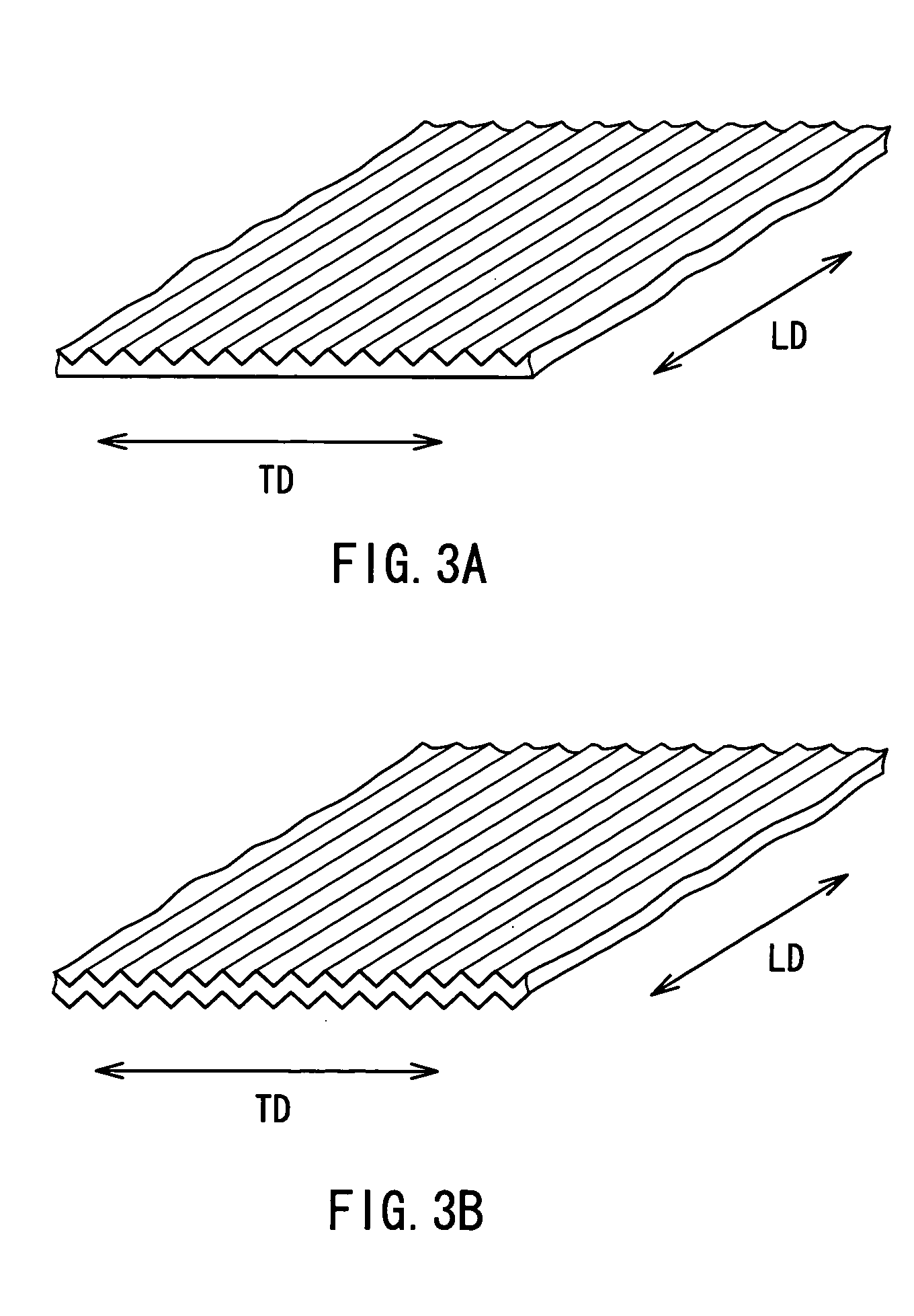
[0059] The PTFE original film obtained by the above-stated process was uniaxially stretched by 12 times in the lengthwise direction. Thereafter, this film was heat-treated at 380° C. for 3 seconds. Thereby, a baked film of 0.2 mm in film thickness and 260 mm in width was obtained. Then, by using the emboss roll having the emboss pattern shown in FIG. 3A and the apparatus of FIG. 4, a zigzag pattern was given to the PTFE film, the zigzag pattern having a pitch interval X between a crest and an adjacent crest of 0.5 mm, a vertical interval Y of 0.6 mm and a zigzag angle θ of 45°.

[0060] The linear pressure of the emboss roll during the emboss processing was 0.8 Kg / cm. The embossing was applied continuously in the lengthwise direction and in the width direction and all over the film.

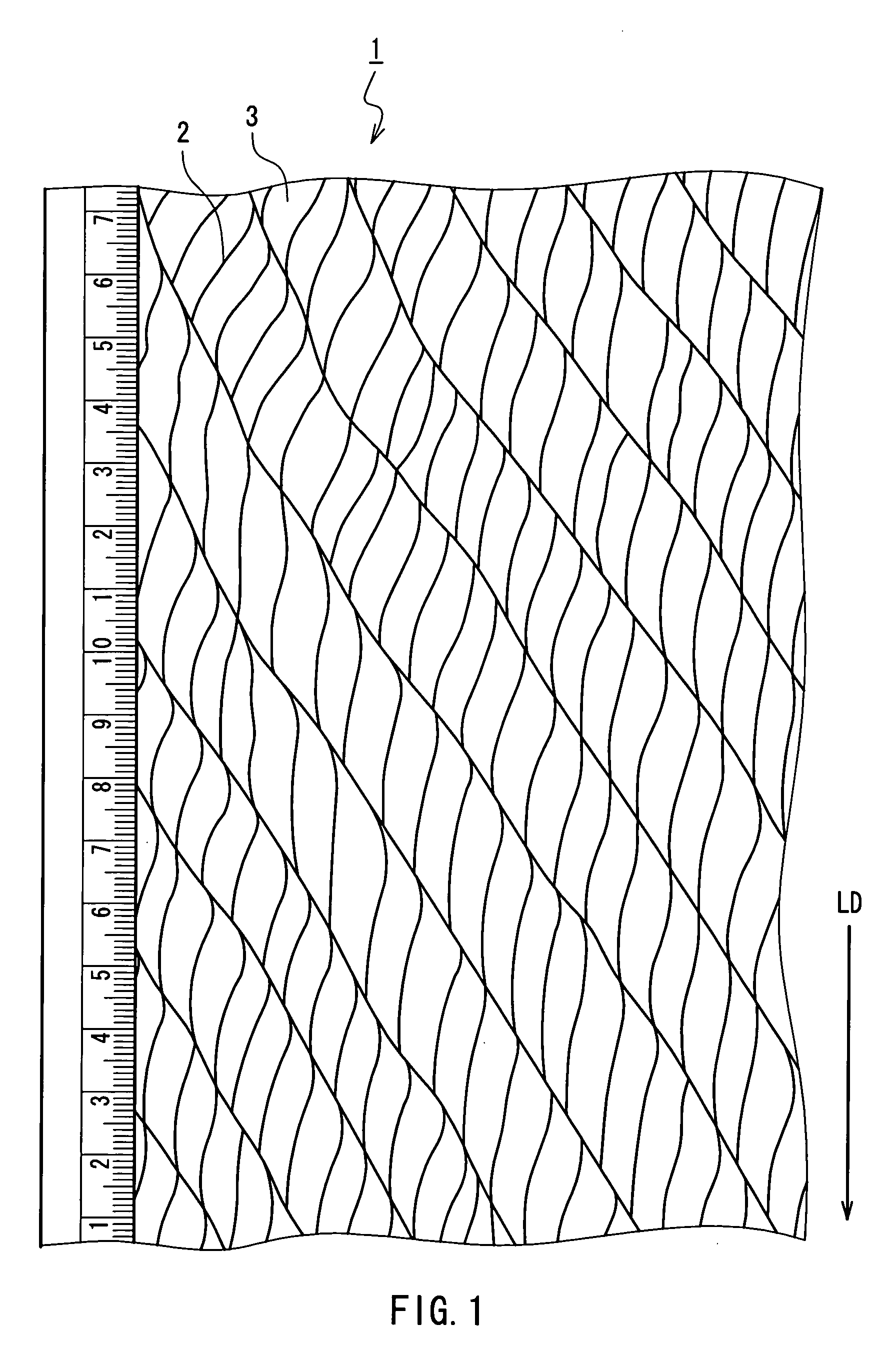
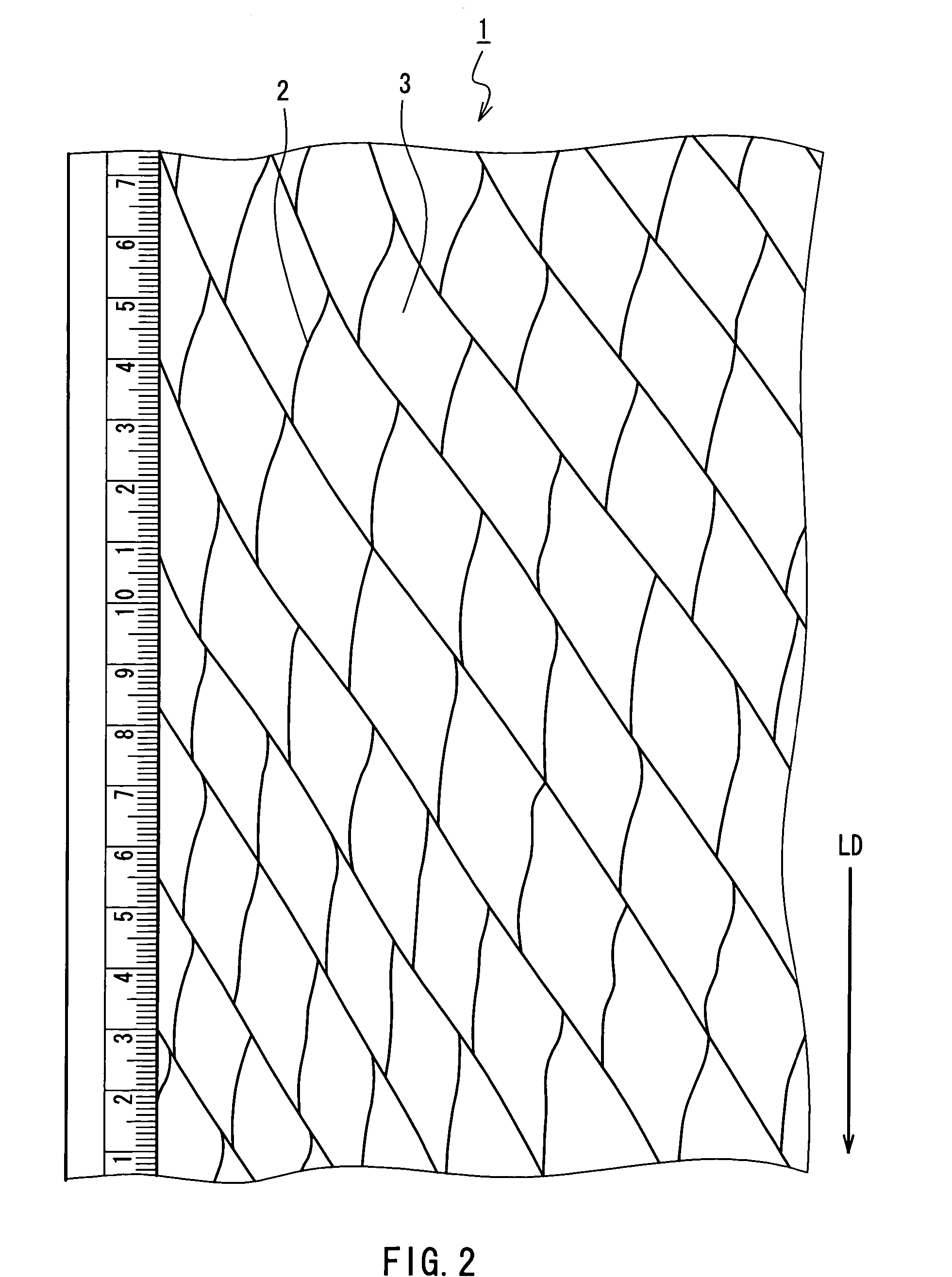
[0061] Next, the PTFE film was fed to a revolving roll with needles so as to slit the film to be opened, whereby a PTFE filament having a network structure was obtained, the network struc...

Example

Working Example 2

[0066] An original film was uniaxially stretched by 9 times in its lengthwise direction, and other conditions were the same as those in Working Example 1 so as to conduct a heat treatment, embossing and opening of the film. Thereby, a PTFE filament having a regular network structure was obtained.

Example

Working Example 3

[0067] A PTFE filament was manufactured under the same conditions as those in Working Example 1 except that an original film was stretched by 6 times in its lengthwise direction, and an interval of the emboss pattern was 0.2 mm and a vertical interval of the emboss was 0.3 mm. The fineness of the filament was 24.2 dtex and the filament was composed of single fibrils forming a regular network structure.


PUM

PropertyMeasurementUnit
Lengthaaaaaaaaaa
Lengthaaaaaaaaaa
Lengthaaaaaaaaaa

Abstract

A polytetrafluoroethylene (PTFE) fiber includes a filament obtained by partially slitting an oriented PTFE film in a lengthwise direction of the film. Emboss processing is conducted linearly along the lengthwise direction of the film and like a zigzag shape or a convexo-concave shape in a width direction of the film, followed by slitting, whereby the filament includes a network structure in which single fibrils that are opened partially are arranged regularly. A PTFE short fiber is obtained by cutting the above filament and includes a branch structure. Thereby, a PTFE fiber with a small average fineness of single fibrils, a uniform fineness and a single-peak distribution with the peak at a center of fineness and with a high production yield and uniform and stable branch structure can be provided and a method for manufacturing the PTFE fiber can be provided.

Description

FIELD OF THE INVENTION [0001] The present invention relates to polytetrafluoroethylene (PTFE) fibers and a method for manufacturing the same. BACKGROUND OF THE INVENTION [0002] Since PTFE resins have a relatively high melting viscosity and are not dissolved by most solvents, fibers cannot be produced by a generally adopted method such as extrusion spinning of molten resins and resin solutions. Therefore, various specific manufacturing methods have been adopted conventionally. U.S. Pat. No. 2,772,444 proposes a method for manufacturing a PTFE fiber by emulsion spinning of a mixed solution of an aqueous dispersion solution of PTFE fine particles and viscose, followed by sintering of the PTFE at high temperatures to remove the viscose by thermal decomposition. However, the manufacturing cost of the PTFE by this method is high, whereas the strength of the fiber obtained is low, and therefore the strength of a product obtained by processing this fiber as a raw material also is low. [0003...

Claims


Application Information

Patent Timeline
IPC IPC(8): D02G3/00D02G3/06
CPCD02G3/06Y10T428/2395Y10T428/31544Y10T428/3154Y10T428/2973Y10T428/2978Y10T428/2913Y10S264/47
Inventor HUANG, JAMESCHOU, CHIN-CHUNCHOU, CHIN-CHACHEN, SHIA-CHUNGKUO, WEN-IHUANG, LEI-TI
Owner YEU MING TAI CHEM INDAL
Why Eureka
Try Eureka