Method and a processor for parallel processing of logic event simulation

a logic event and processor technology, applied in the field of logic event simulation processing processors, can solve the problems of overly simplistic intrinsic unit delay models of compiled code simulators, affecting the overall performance of the system, and achieving significant speed up, so as to improve the speed of the processor, reduce time wastage, and enhance the effect of processing speed

Inactive Publication Date: 2005-10-13
NEOSERA SYST
View PDF2 Cites 7 Cited by
  • Summary
  • Abstract
  • Description
  • Claims
  • Application Information

AI Technical Summary

Benefits of technology

[0006] This led to a parallel processing method of logic event simulation incorporating an associative memory mechanism as described in the Applicants own PCT Patent Application No. WO 01 / 01298. In WO 01 / 01298 the Applicant describes using a parallel processing method of logic event simulation with an associative memory mechanism in which the history of values on a particular line may be stored as a bit sequence and gate evaluations may be carried out on these bit sequences in both hardware and software resulting in superior speed up figures for parallel processing.
[0104] In a further embodiment of the invention there is provided a processor in which there is provided a segment address table, the segment address table is divided into a number of rows, each row being M bits long, and each segment address is stored in the most significant M-D bits of the segment row when the number of segments is equal to 2D. This is a simple and efficient way of addressing the segments in a uniform manner.

Problems solved by technology

One of the problems encountered in the field of parallel processing has been achieving significant speed up figures commensurate to the additional processing power available for simulation.
Although impressive speed of figures for the methods have been reported, they are often misleading as gates that are not active or being evaluated as well and therefore the actual processing power is only a fraction of that reported.
However the intrinsic unit delay model of compiled code simulators is overly simplistic for many applications.
However, overall performance has been disappointing and usually speed of figures ranging from 3 to 5 have been achieved.
Unfortunately, these mechanisms themselves contribute large overhead communication costs for even modest sized parallel systems.
This leads to a reduction in the speed of figures and a rather complex system.
Furthermore, the gate evaluation process incurs between 10 and 250 machine cycles per gate evaluation, which is time consuming and costly to the processing capability of the machine.
However, both of these approaches were still found to be insufficient to warrant the increase in the amount of additional processing power provided for the gain in speed-up times achieved.
There were however a number of problems with the parallel processing method of logic event simulation using an associative memory mechanism.
The main problem with the approach taken in WO 01 / 01298 was that the size of circuit to be evaluated was limited by the size of the associative memory mechanism associative arrays.
By simply increasing the size of the associative arrays the design became unwieldy and difficult to manage.
Conventional Cache Memory Mechanisms were heretofore unsuitable for use with such a method of parallel processing of logic event simulation.
Usually there is a probability as high as 90% or more that the correct memory block is brought in but this would not be acceptable in the associative memory mechanism provided.
Such a system also wastes valuable processing time when a reference is made to a particular block that has not been brought in from external memory at the appropriate time.
Another difficulty experienced by the Applicants was that the number of tests that could be carried out on gates pairs in the associative arrays was limited by the number of bits per word in the Group-Result Register Bank (GRRB).
In addition to the above it was further discovered that valuable processing time was being taken up in the evaluation of the interconnect lines thereby putting further demands on the processing time of the parallel processor.
Also, there was no way of modelling synchronous devices as they were to complex to manage in the known parallel processing method of logic event simulation.
All of these meant that although a significant advance had been made over the prior art in achieving speed up figures for the parallel processing method the device was still impractical for everyday application.

Method used


Image

  • Method and a processor for parallel processing of logic event simulation
  • Method and a processor for parallel processing of logic event simulation
  • Method and a processor for parallel processing of logic event simulation

Examples


Embodiment Construction

[0106] The invention will now be more clearly understood from the following description of some embodiments thereof given by way of example only with reference to the accompanying drawings in which:—

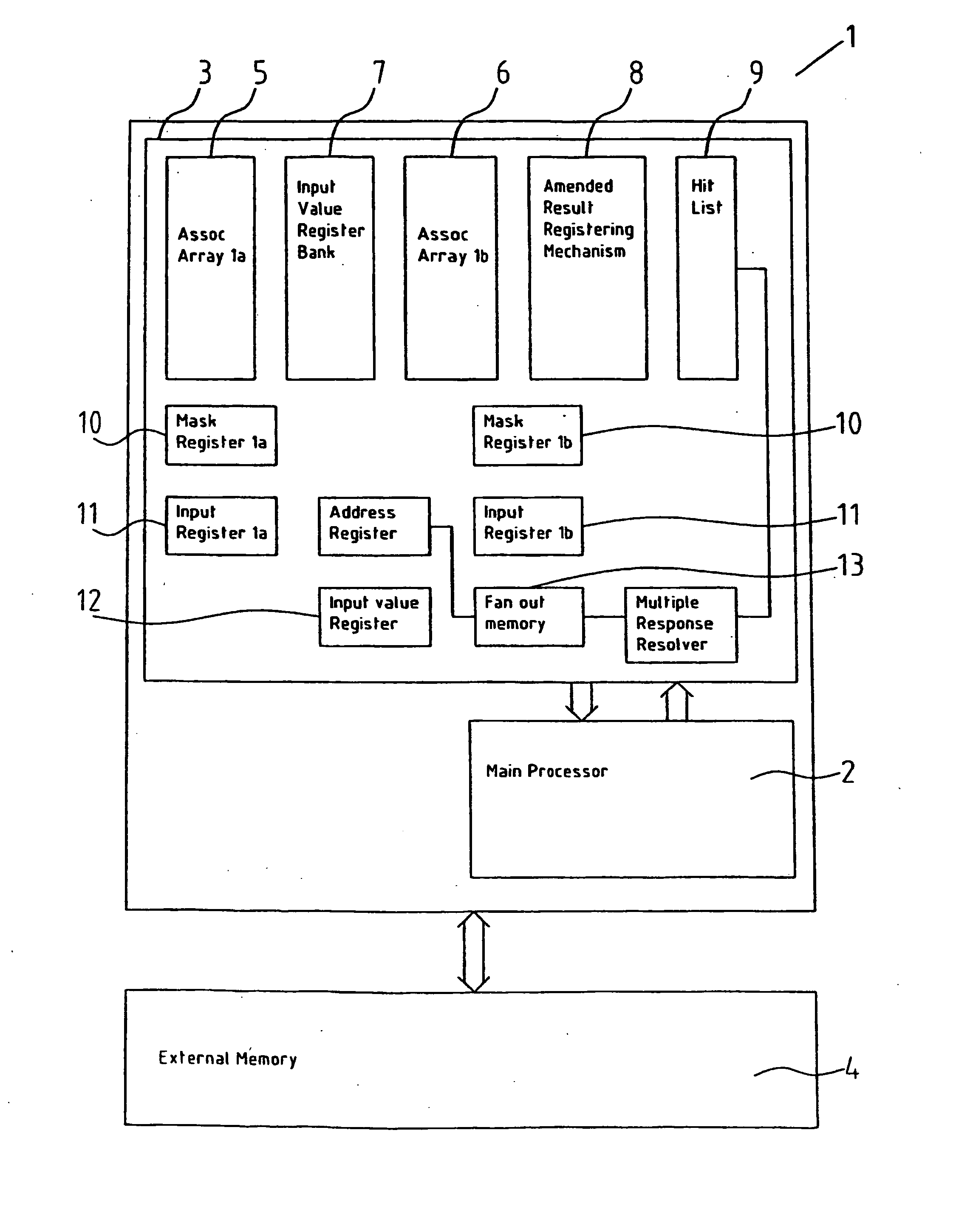
[0107]FIG. 1 is a block diagram of a processor for parallel processing of logic event simulation;

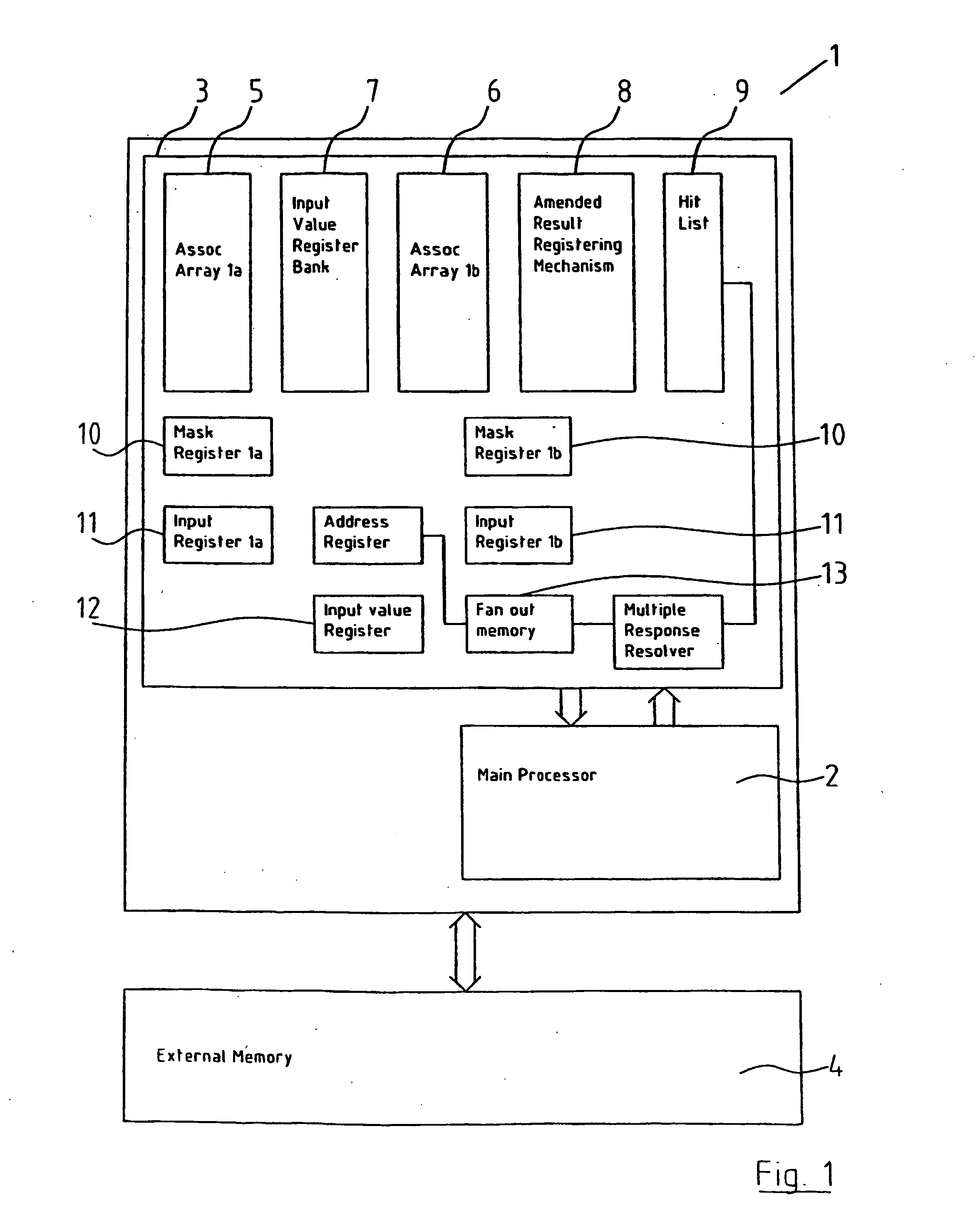
[0108]FIG. 2 is a block diagram of the segment table;

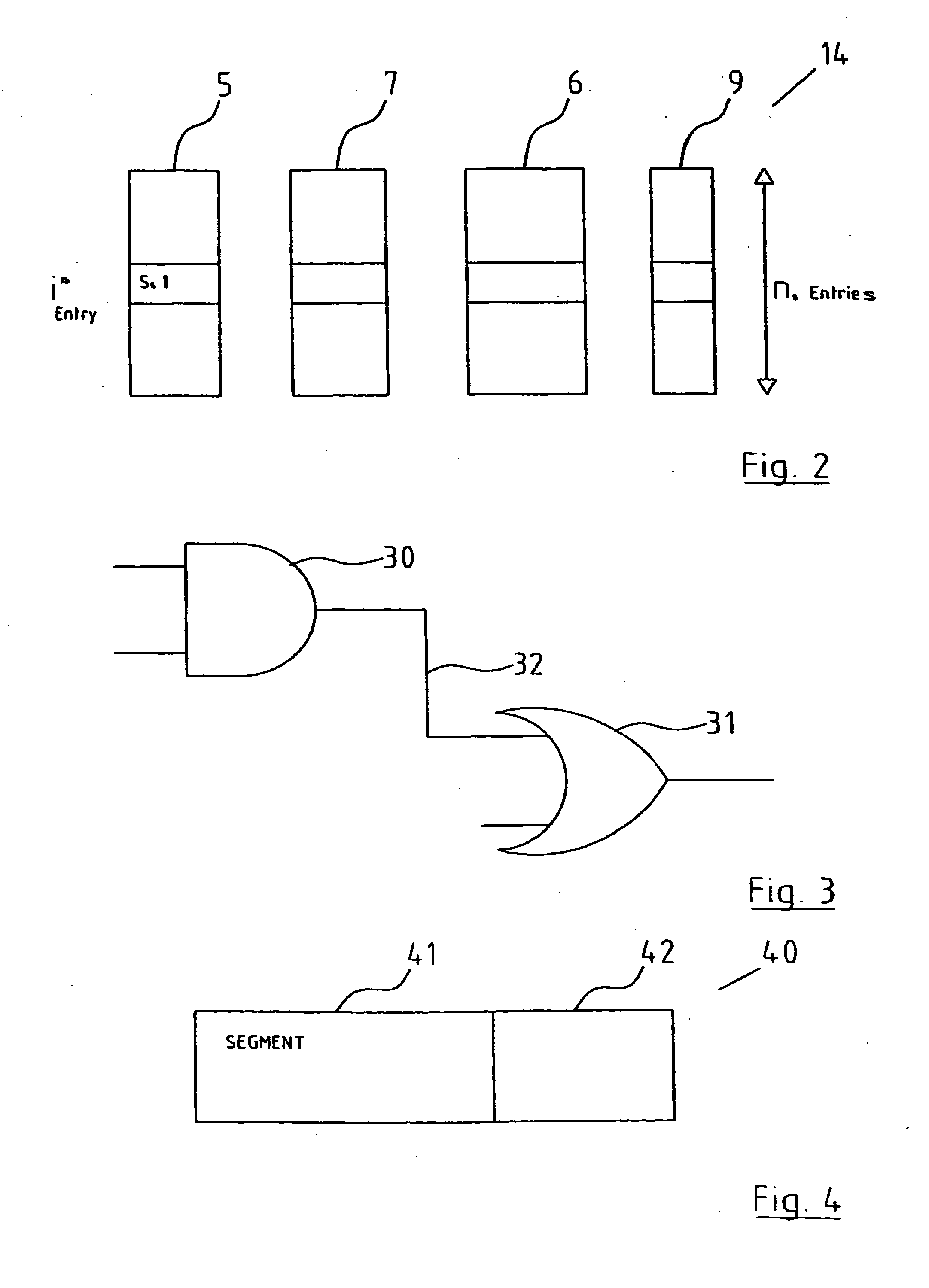
[0109]FIG. 3 illustrates a pair of logic gates, one of which being the fan-out gate of the other;

[0110]FIG. 4 illustrates the incorporation of segment addresses in fan-out addresses;

[0111]FIG. 5 is a logic gate representation of the result polarity circuit;

[0112]FIG. 6 is a logic gate representation of the logic combination circuit;

[0113]FIG. 7 is a logic gate representation of the amended result registering mechanism;

[0114]FIG. 8 is a timing diagram showing the set-up and hold times of a synchronous device;

[0115]FIG. 9 is a block diagram of a gate input addressing technique; and

[0116]FIG. 10 is a block diagram of a scan system for...


PUM


Abstract

A method and a processor for parallel processing of logic event simulation on circuits comprising a polarity of logic gates, the logic gates having interconnect lines therebetween, the processor (1) further comprising a main processor (2) and an associative memory mechanism (3), the associative memory mechanism (3) comprising a plurality of associative arrays (5, 6) and at least one result register, and there is provided accessible external memory (4) in which a circuit representation may be stored and divided into a plurality of segments, each of the segments having a segment identifier, which in turn has segment data associated therewith. The segment identifier and segment data being stored in a segment table (14) in the associative memory mechanism. Each of the segments may then be brought into the associative memory mechanism (3) for evaluation one at a time. There is additionally provided an amended result registering mechanism (8) to allow numerous tests and gate pairs to be carried out and recorded.

Description

[0001] This invention relates to a processor for parallel processing of logic event simulation and a parallel processing method of logic event simulation on circuits comprising a plurality of logic gates, the logic gates having interconnect lines therebetween, the method being carried out in a main processor and an Associative Memory Mechanism, the Associative Memory Mechanism comprising a plurality of associative arrays and at least one result register. [0002] One of the problems encountered in the field of parallel processing has been achieving significant speed up figures commensurate to the additional processing power available for simulation. There have been many different approaches to solving this problem including the use of compiled code and event driven simulation in which a circuit is partitioned amongst processors. In compiled code simulation all gates are evaluated at all time steps even if they are not active. The circuit has to be levellised and only unit or zero dela...

Claims


Application Information

Patent Timeline
Patent Type & Authority Applications(United States)
IPC IPC(8): G06F17/50
CPCG06F17/5022G06F30/33
Inventor DALTON, DAMIAN
Owner NEOSERA SYST
Why Eureka
Try Eureka