Linear hearth furnace system and methods regarding same

a furnace system and linear technology, applied in the field of linear furnace systems and methods regarding same, can solve the problems of difficult feed distribution to the rhf, general non-uniform heat treatment of such balls in the rhf, and inherently fragile balls, etc., to facilitate the repair of the linear furnace apparatus

Active Publication Date: 2005-10-20
NU IRON TECH LLC
View PDF36 Cites 53 Cited by
  • Summary
  • Abstract
  • Description
  • Claims
  • Application Information

AI Technical Summary

Benefits of technology

[0020] In another embodiment, at least one of the preheat zone, the furnace zone, and the cooling zone is configured using multiple modular linear sections corresponding to the particular zone being configured to allow lengthening or shortening of the at least one zone along the longitudinal axis. The use of modular linear sections may also facilitate repair of the linear furnace apparatus. Further, the linear furnace apparatus may include one or more conduits that allow movement of one or more gases between one or more of the preheat zone, the furnace zone, the cooling zone, and sub-zones thereof.

Problems solved by technology

Various issues related to the design of such furnaces (e.g., those used to produce DRI or metallic iron nuggets) include, but are clearly not limited to, material handling, engineering / construction, maintenance, flue gas treatment to remove particulates and recover sensible heat, and in some cases provide it as make-up gas, hearth integrity, and overall system reliability.
For example, feed distribution to the RHF is difficult because of the difference between the annular speed of the near and far sides of the hearth.
Such balls are inherently fragile, especially when they contain nearly 40% volume of pulverized coal.
Heat treatment of such balls in a RHF is generally non-uniform, i.e., balls on the short radius of the annular hearth receive intense direct radiation from wall burners for an appreciably greater length of time than those on the outer radius.
Further, discharge of such balls from the hearth requires that they maintain their physical integrity after reduction, which is often a problem.
The balls are, for example, augered off the annular hearth and breakage could lead to jamming of the rotary hearth, damage to the hearth, or damage to an auger used for such discharge.
Various other limitations of the RHF relate to its physical construction.
For example, the physical arrangement of a RHF necessarily leads to the cold feed side being next to the hot discharge side resulting in congestion and material handling complications.
Further, the circular arrangement makes construction difficult (e.g., refractory, side walls, burners all have to be configured in a circular design) and the center of the RHF is congested and difficult to access for maintenance.
Further, the design of the RHF, due to its circular arrangement, has size limitations placed thereon (e.g., about 60 meters diameter).
For example, the hearth is generally massive and as such, problems in rotating such a large hearth increase with its size.
However, the PSH furnace also has associated problems.
Further, in the PSH furnace, it is necessary to duplicate both charge delivery and product removal systems at each end of the furnace.
This requires a complicated distribution system, or, for example, doubling the charge metering system for multiple components and the blending and drying systems.

Method used


Image

  • Linear hearth furnace system and methods regarding same
  • Linear hearth furnace system and methods regarding same
  • Linear hearth furnace system and methods regarding same

Examples


Embodiment Construction

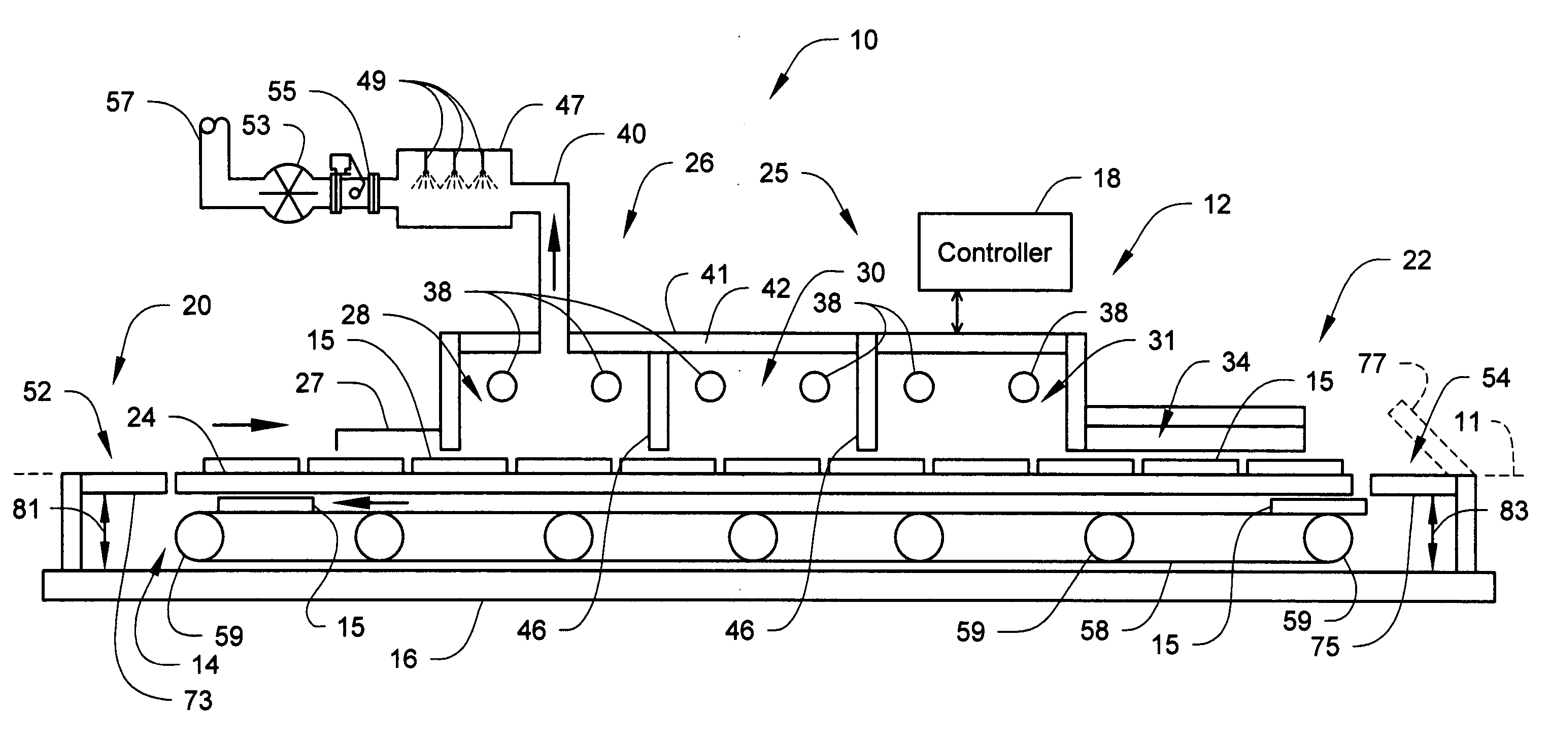
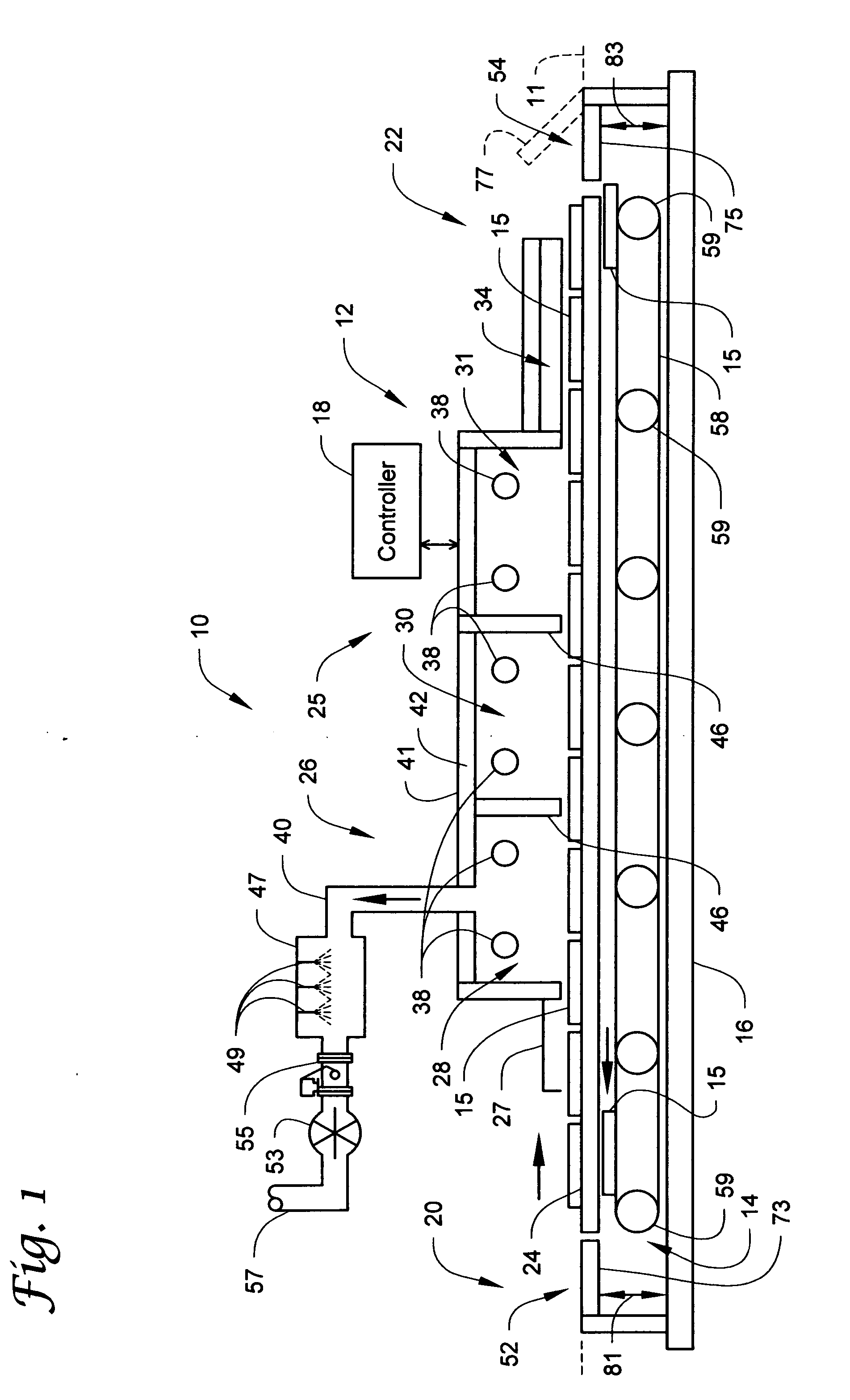
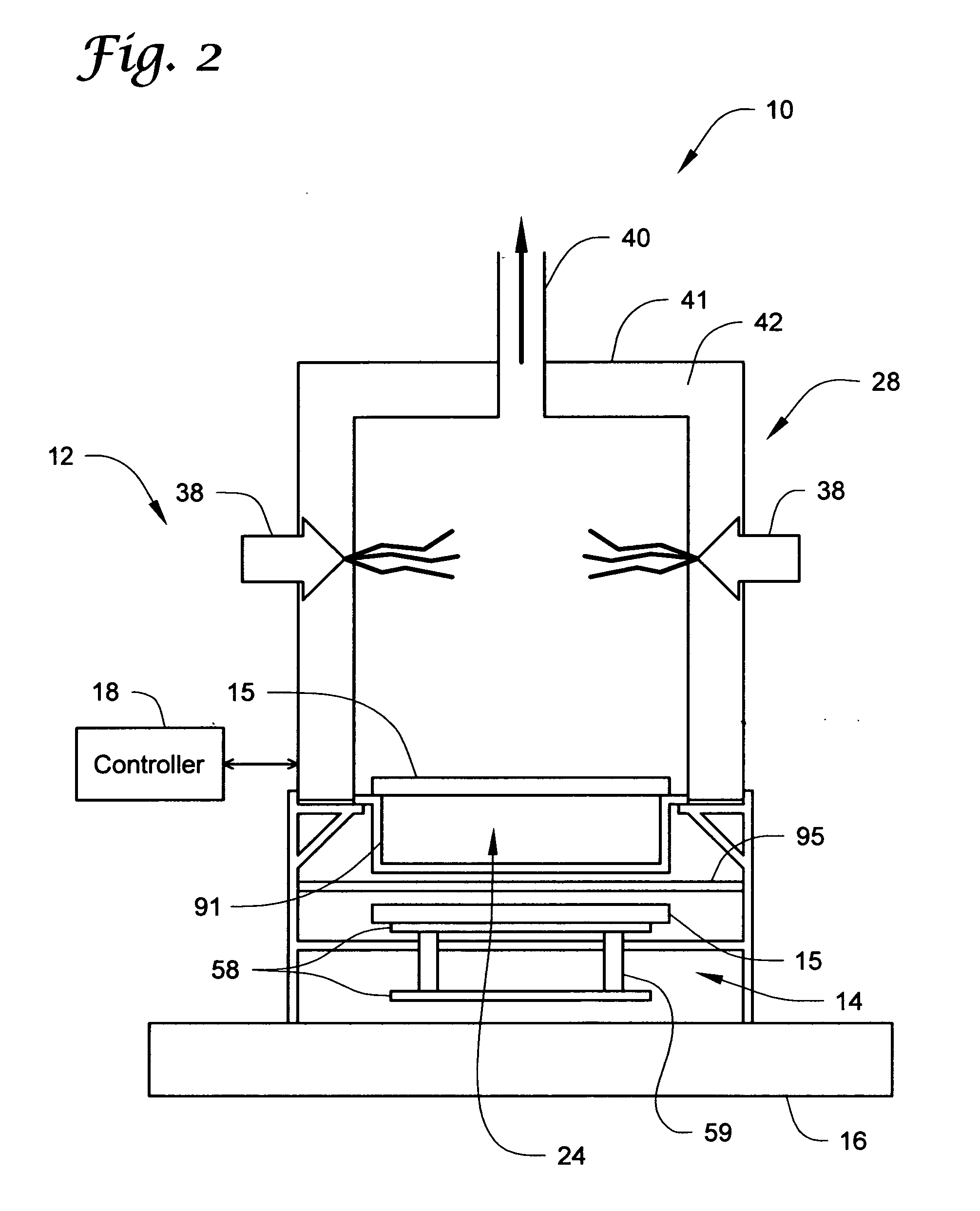
[0040] The present invention shall generally be described with reference to FIGS. 1-5. One or more detailed embodiments of the present invention shall then be described with reference to FIGS. 6-9. It will become apparent to one skilled in the art that elements from one embodiment may be used in combination with elements of the other embodiments, and that the present invention is not limited to the specific embodiments described herein but only as described in the accompanying claims. Further, it will be recognized that the embodiments of the present invention described herein will include many elements that are not necessarily shown to scale.

[0041]FIG. 1 shows a side cross-sectional view of a linear hearth furnace (LHF) system 10 according to the present invention for use in processing raw material. The LHF system 10 includes a linear furnace apparatus 12 extending along a longitudinal axis 11 between a charging end 20 and a discharging end 22. The linear furnace apparatus 12 incl...


PUM

PropertyMeasurementUnit
diameteraaaaaaaaaa
temperaturesaaaaaaaaaa
temperatureaaaaaaaaaa

Abstract

Systems and methods for use in processing raw material (e.g., iron bearing material) include a linear furnace apparatus extending along a longitudinal axis between a charging end and a discharging end (e.g., the linear furnace apparatus includes at least a furnace zone positioned along the longitudinal axis). Raw material is provided into one or more separate or separable containers (e.g., trays) at the charging end of the linear furnace apparatus. The separate or separable containers are moved through at least the furnace zone and to the discharging end where the processed material is discharged resulting in one or more empty containers. One or more of the empty containers are returned to the charging end of the linear furnace apparatus to receive further raw material.

Description

CROSS-REFERENCE TO RELATED APPLICATIONS [0001] This application claims the benefit of U.S. Provisional Application Ser. No. 60 / 558,197 filed 31 Mar. 2004, which is incorporated herein by reference in its entirety.STATEMENT OF GOVERNMENT RIGHTS [0002] The present invention was made with support by the Economic Development Administration, Grant No. 06-69-04501. The government may have certain rights in the invention.BACKGROUND OF THE INVENTION [0003] The present invention relates to systems, apparatus, and / or methods for use in the processing of metal bearing material (e.g., the reduction of iron bearing materials such as iron oxide using a direct reduction process). [0004] Hearth furnaces have been manufactured for decades and present a proven technology for various purposes, including reduction of metal bearing materials. Such furnaces have been widely used in the mineral industry for drying, preheating, roasting, calcining, steel plant waste treatment, iron ore reduction, and produ...

Claims


Application Information

Patent Timeline
Patent Type & Authority Applications(United States)
IPC IPC(8): C21B11/00C21C5/56F27B9/02F27B9/24F27B9/26F27B9/38F27B9/39F27D3/00F27D3/02F27D3/12F27D5/00
CPCC21B11/00F27D2003/0065C21B13/10C21C5/567F27B9/024F27B9/028F27B9/2407F27B9/243F27B9/26F27B9/38F27B9/39F27B9/40F27D3/003F27D3/02F27D3/12F27D3/123F27D5/0068F27D19/00C21B11/08
Inventor BLEIFUSS, RODNEY L.ENGLUND, DAVID J.KIESEL, RICHARD F.
Owner NU IRON TECH LLC
Why Eureka
Try Eureka