Polymer based distributive waveguide sensor for pressure and shear measurement

a distributed waveguide and sensor technology, applied in the field of sensors, can solve the problems of low sensitivity, large deflection, and unsuitable array use of gages, and achieve the effect of high spatial resolution

a distributed waveguide and sensor technology, applied in the field of sensors, can solve the problems of low sensitivity, large deflection, and unsuitable array use of gages, and achieve the effect of high spatial resolution

US20050232532A1Inactive Publication Date: 2005-10-20UNIV OF WASHINGTON

Image

  • Polymer based distributive waveguide sensor for pressure and shear measurement
  • Polymer based distributive waveguide sensor for pressure and shear measurement
  • Polymer based distributive waveguide sensor for pressure and shear measurement

Examples


Embodiment Construction

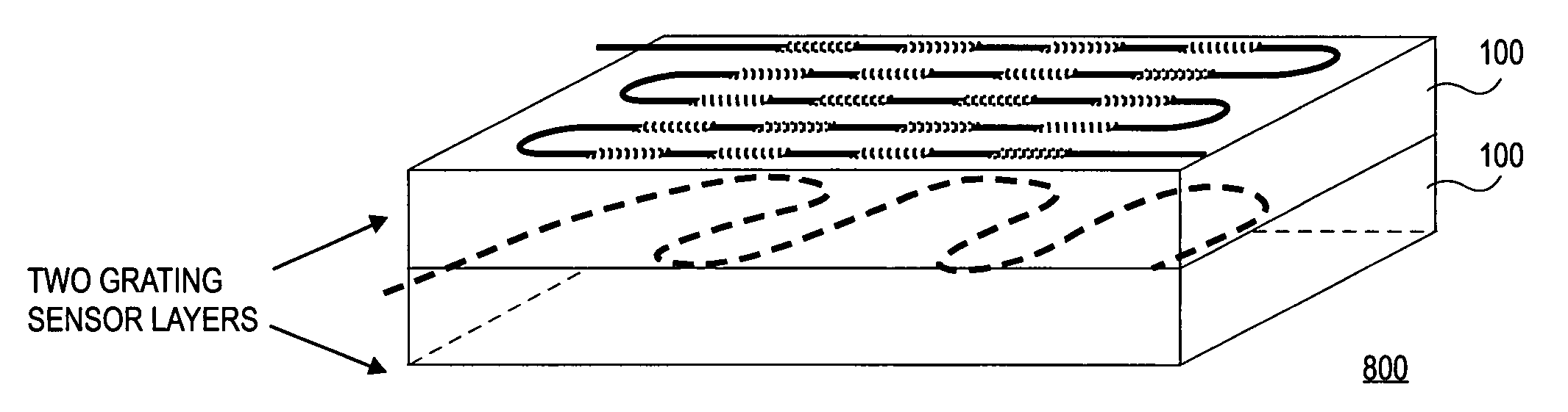
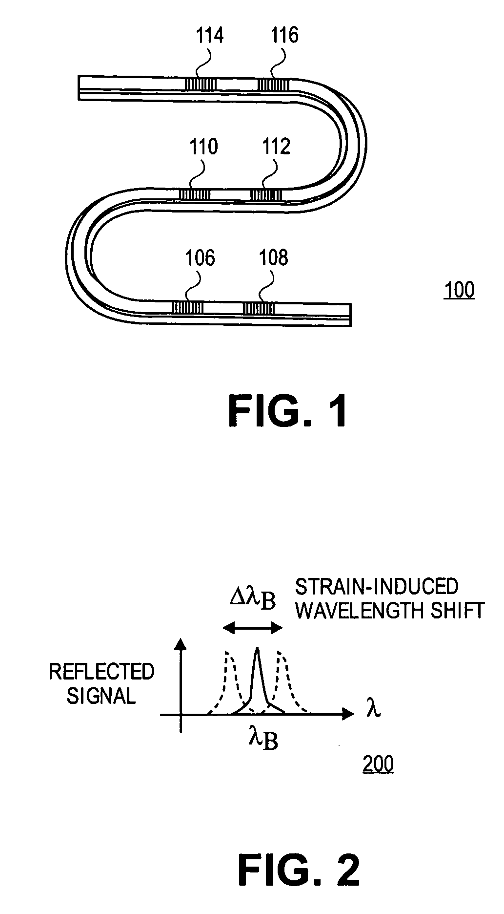
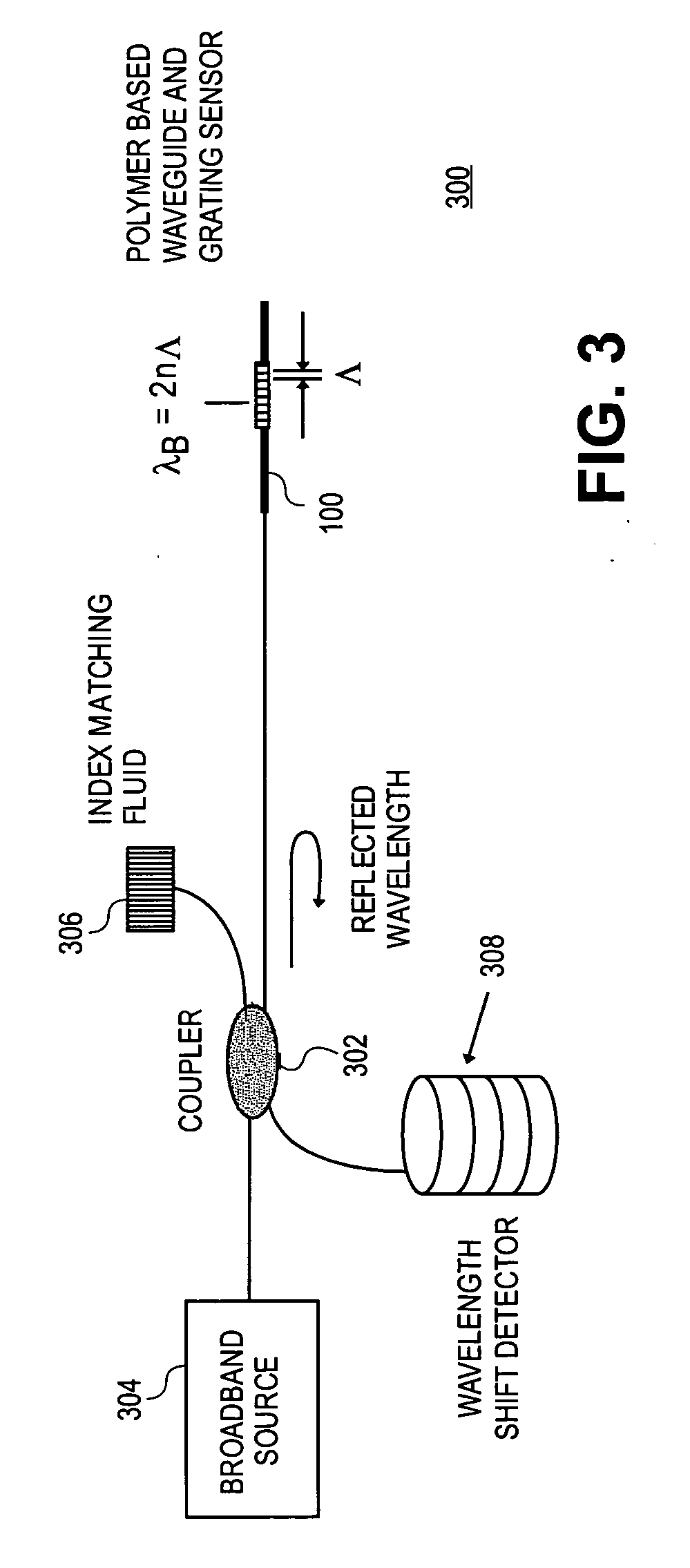
[0013] In embodiments of the present invention, an apparatus is defined for providing measurement of pressure and / or shear stress over an area using a flexible polymer-based Bragg grating sensor. This sensor may be an innovative use of existing waveguide technology and micro-electromechanical system (MEMS) fabrication techniques. The sensor may have high spatial resolution and be able to conform to and be embedded into a structure of interest. Using Bragg grating technology will allow collection of data from a large number of pressure points within the sensor using only a small number of input and output channels. By using highly compliant silicone rubber as the optical waveguide, the sensor system may be able to conform to the structure of interest. Polymer materials used here are biocompatible (i.e. silicone rubber) and have a mechanical impedance to the plantar soft tissue.

[0014] In one embodiment, a pressure sensor includes a flexible substrate. A waveguide may be disposed in o...


PUM


Abstract

According to embodiments of the present invention, a distributed pressure and shear stress sensor includes a flexible substrate, such as PDMS, with a waveguide formed thereon. Along the waveguide path are several Bragg gratings. Each Bragg grating has a characteristic Bragg wavelength that shifts in response to an applied load due to elongation / compression of the grating. The wavelength shifts are monitored using a single input and a single output for the waveguide to determine the amount of applied pressure on the gratings. To measure shear stress, two flexible substrates with the waveguide and Bragg gratings are placed on top of each other such that the waveguides and gratings are perpendicular to each other. To fabricate the distributive pressure and shear sensor, a unique micro-molding technique is used wherein gratings are stamped into PDMS, for example.

Description

CROSS REFERENCE TO RELATED APPLICATIONS [0001] This application claims the benefit of U.S. Provisional Application No. 60 / 548,965, filed Mar. 1, 2004.BACKGROUND [0002] 1. Field [0003] Embodiments of the present invention relate to sensors and, in particular, to pressure and shear sensors. [0004] 2. Discussion of Related Art [0005] Investigation in tactile sensing has been an active research area for the past 30 years. The technologies applied to date in the tactile sensing field include metal strain gages, conductive elastomers, carbon fibers, conductivity measurement (usually in association with elastomers), ferroelectric polymers (i.e., PVF2), semiconductor strain gages, magnetostriction, capacitance and optoelectronics. The characteristics of all tactile sensors depend, to some degree, on the properties of the deformable contact material. Each material has its advantages and disadvantages, depending on physical properties and manufacturing concerns. Conventional metal strain gage...

Claims


Application Information

Patent Timeline
20 Oct 2005
Publication
US20050232532A1
IPC
A61B5/103; G01B11/16; G01D5/353; G01L1/24; G02B6/02; G02B6/12; G02B6/132; G02B6/34
CPC
A61B5/1036; A61B5/6892; A61B2562/0266; G01D5/35303; G02B2006/12176; G02B6/12007; G02B6/132; G02B2006/12107
Inventors
WANG, WEI-CHIH; REINHALL, PER G.