
Biosensor

a biosensor and sensor technology, applied in the field of compact and disposable biosensors, can solve the problems of inability to obtain accurate measurement results, inability to obtain high-quality measurement values, and inability to achieve accurate measurement results

Active Publication Date: 2005-10-27
PHC HLDG CORP
View PDF4 Cites 108 Cited by
  • Summary
  • Abstract
  • Description
  • Claims
  • Application Information

AI Technical Summary

Benefits of technology

[0021] The present invention is made to solve the above-mentioned problems and has for its object to provide a biosensor which can suck a sufficient quantity of specimen regardless of the viscosity of the supplied specimen, and is provided with a minute air hole from which the specimen does not overflow.

Problems solved by technology

If a biosensor with the residue remaining in the air hole 49 is produced, a sufficient amount of specimen supplied cannot be drawn in the biosensor, resulting in a problem relating to measurement precision.
However, when the size of the air hole to be formed in the second support 48 using the laser processing is too small, if the specimen supplied to the biosensor is a control solution or the like having a relatively low viscosity, since the speed at which the specimen is drawn into the specimen supply path 7 is too high as compared with the speed at which the air collected in the specimen supply path 47 gets out of the air hole 49, air bubbles remain in the specimen supply path 47 and thereby a sufficient amount of specimen cannot be drawn, resulting in a new problem that accurate measurement result cannot be obtained, although there occurs no problem when the specimen supplied to the biosensor is blood or the like having a relatively high viscosity.
Further, in the conventional biosensor 400 having the construction as described above, when a minute air hole 49 is formed and a specimen having a significantly low viscosity or a control solution is supplied to the air hole so as to be drawn into the specimen supply path 47, the supplied specimen as well as the dissolved reagent flow out of the air hole 49, whereby the measurement value to be detected by the measurement apparatus is lowered, resulting in a problem that highly accurate measurement value cannot be obtained.
However, prevention of overflow of the liquid specimen from the air hole 49 by the above-mentioned method takes much time and cost for applying the water-shedding material on the second support 48.

Method used


Image

  • Biosensor
  • Biosensor
  • Biosensor

Examples


embodiment 1

(Embodiment 1)

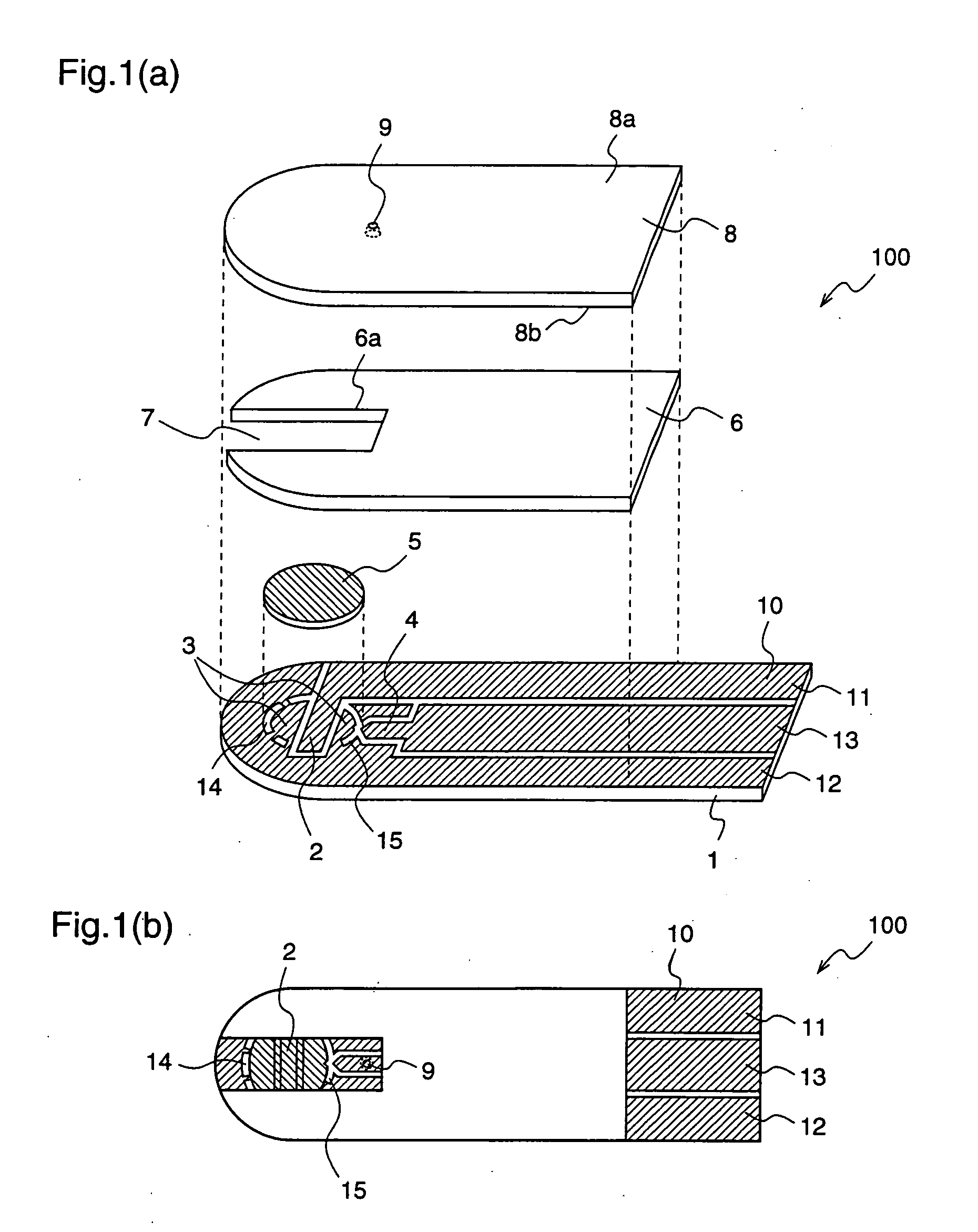
[0044] Hereinafter, a biosensor 100 according to a first embodiment of the present invention will be described with reference to the drawings. FIG. 1(a) is an exploded perspective view of a biosensor, and FIG. 1(b) is a plan view of the biosensor shown in FIG. 1(a).

[0045] With reference to FIGS. 1(a) and 1(b), reference numeral 1 denotes a first insulating support (hereinafter referred to as “first support”) comprising polyethylene terephthalate or the like, and a conductive layer 10 comprising an electrical conductive material such as a noble metal (e.g., gold or palladium) or carbon is formed on the surface of the first support 1 by screen printing, sputtering evaporation, or the like. The conductive layer 10 is formed over the entire surface or at least a part of the first support 1.

[0046] On the first support 1, the conductive layer 10 is divided by plural slits, thereby providing a counter electrode 3, a measurement electrode 2, a detection electrode 4, and reag...


PUM

PropertyMeasurementUnit
thicknessaaaaaaaaaa
diameteraaaaaaaaaa
diameteraaaaaaaaaa

Abstract

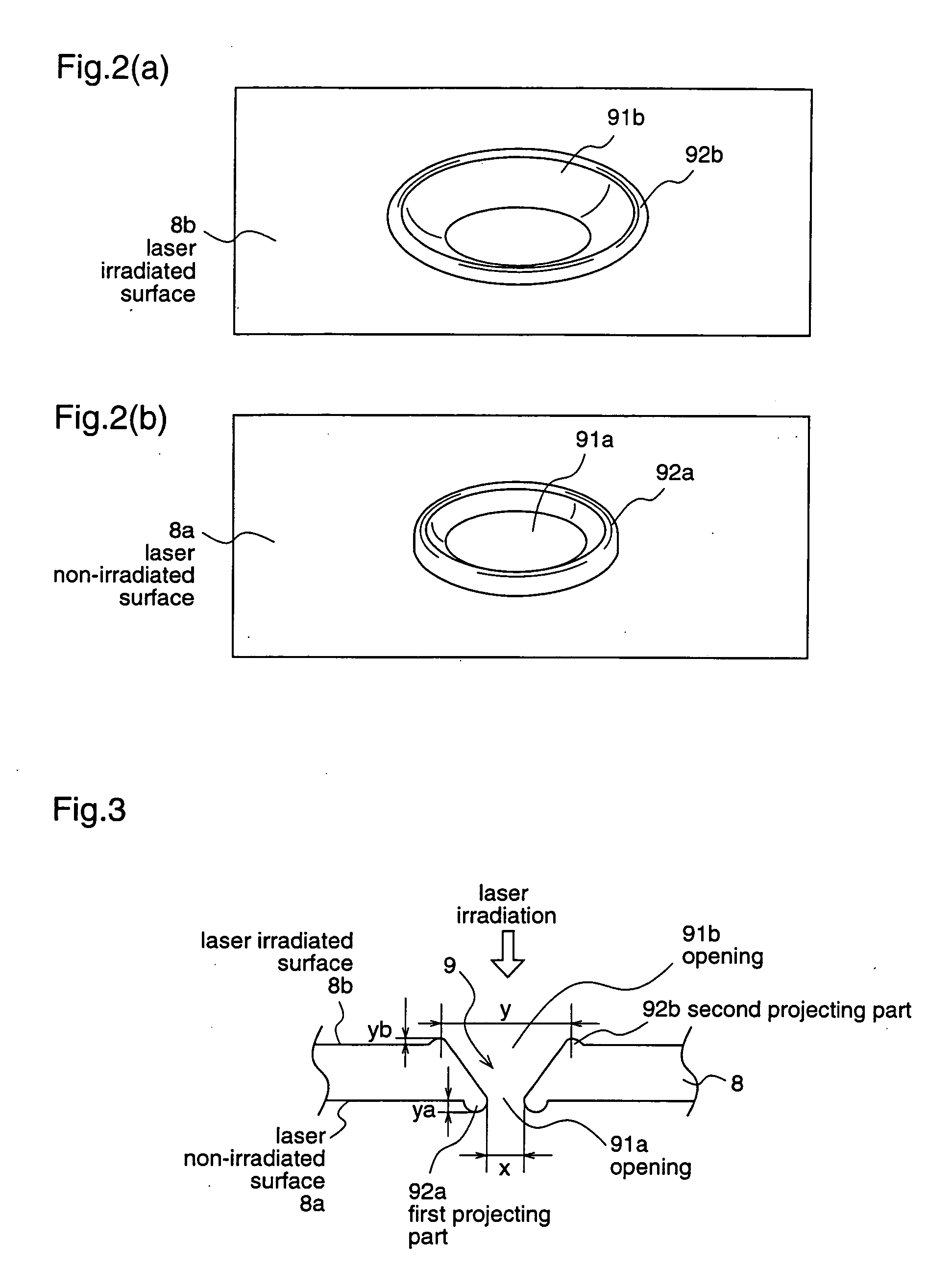
There is provided a biosensor in which a spacer 6 having a cutout portion is bonded between at least first support 1 and a second support 8 to form a specimen supply path 7 through which a supplied specimen is sucked into a space between the supports 1 and 8, a reagent that reacts with a component in the specimen is placed in the specimen supply path 7, and an air hole 9 for promoting suction of the specimen is formed in the second support; wherein the air hole 9 is shaped such that a diameter y of an opening 91b at one surface of the second support 8 which faces the specimen supply path 7 is larger than a diameter x of an opening 91a at the other surface of the second support, and projecting parts 92a and 92b are formed at the peripheries of the openings 91a and 91b, respectively. Thereby, a sufficient amount of specimen can be sucked regardless of the viscosity of the specimen supplied to the biosensor, and further, the specimen is prevented from flowing over the air hole 9.

Description

FIELD OF THE INVENTION [0001] The present invention relates to a compact and disposable biosensor which can analyze a specific component in a liquid sample by utilizing a reaction between the liquid sample and a reagent and, more particularly, to a biosensor which can provide a highly precise measurement result. BACKGROUND OF THE INVENTION [0002] A biosensor is a sensor which utilizes a molecule recognizing ability of a biological material such as micro-organisms, enzymes, antibodies, DNA, RNA and the like, and applies a biological material as a molecule recognition element. To be specific, it utilizes a reaction which is caused when an immobilized biological material recognizes an objective substrate, such as enzyme consumption due to respiration of a micro-organism, enzyme reaction, light emission, and the like. Among various biosensors, an enzyme sensor has progressively come into practical use, and an enzyme sensor for glucose, lactic acid, uric acid, and amino acid, has been ut...

Claims


Application Information

Patent Timeline
Patent Type & Authority Applications(United States)
IPC IPC(8): C12M1/34C12Q1/00G01N27/26G01N33/487G01N33/50H10N99/00
CPCG01N27/3272C12Q1/001
Inventor TAKAHASHI, KOJIHIGASHIHARA, AKIHISA
Owner PHC HLDG CORP
Learn More