Styryl dyes

a technology of styryl dyes and dyes, which is applied in the field of organic dye compounds, can solve the problems of low storage density of organic dyes, inability to meet the high-density requirements of many fields, and easy change of recording layers in environmental ligh

Inactive Publication Date: 2005-10-27
KABAYUSHI KAISHI HAYASHIBARA SEIBUTSU KAGAKU KENKYUJO
View PDF11 Cites 48 Cited by
  • Summary
  • Abstract
  • Description
  • Claims
  • Application Information

AI Technical Summary

Benefits of technology

[0007] The present inventors eagerly studied and screened compounds. As a result, they found that specific styryl dyes (may be called “styryl dyes” hereinafter), which are obtainable through a step of reacting a quaternary ammonium salt of nitrogen heterocyclic compound having an active methyl- or active methylene-group with an aldehyde compound, have absorption maxima at a wavelength of 400 nm or less and substantially absorb visible light with a wavelength a

Problems solved by technology

When compared with inorganic optical recording media, organic ones may have the drawback that their recording layers are susceptible to change under environmental lights such as reading and natural light.
However, since most or

Method used


Image

  • Styryl dyes
  • Styryl dyes
  • Styryl dyes

Examples


example 1

Styryl Dye

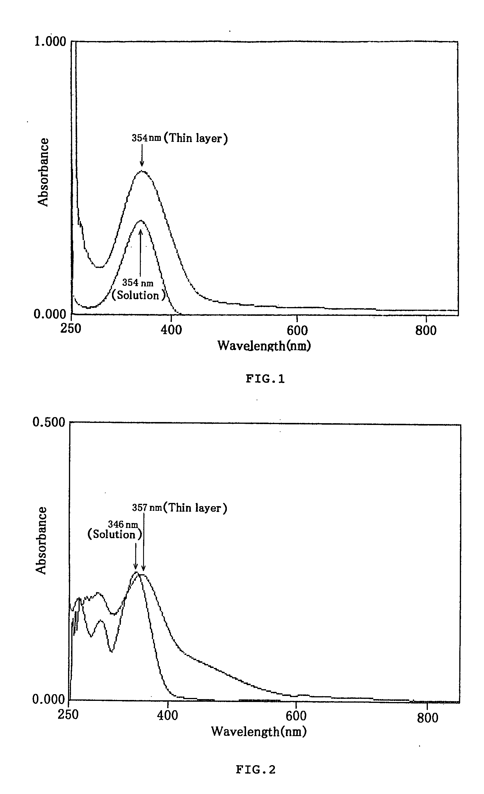
[0040] Twenty milliliters (ml) of acetic anhydride and 0.6 ml of triethylamine were placed in a reaction vessel, and mixed with 4 g of 2,3,4-trimethylthiazolium=iodide and 2 g of 4-cyanobenzaldehyde. The resulting mixture was reacted at 80° C. for one hour under stirring conditions, and then was cooled down. The crystals formed were collected, washed with ethanol, dissolved in a solution of methanol and chloroform under heating, and then filtered. The obtained filtrate was distilled to remove chloroform and cooled down to obtain 1.1 g of a yellow crystal of the styryl dye represented by Chemical Formula 9. When measured in a conventional manner, the melting point of the crystal was 261-263° C.

[0041] The styryl dye of this Example with remarkable optical properties has various uses in many fields including those of optical recording media as a light absorbent.

example 2

Styryl Dye

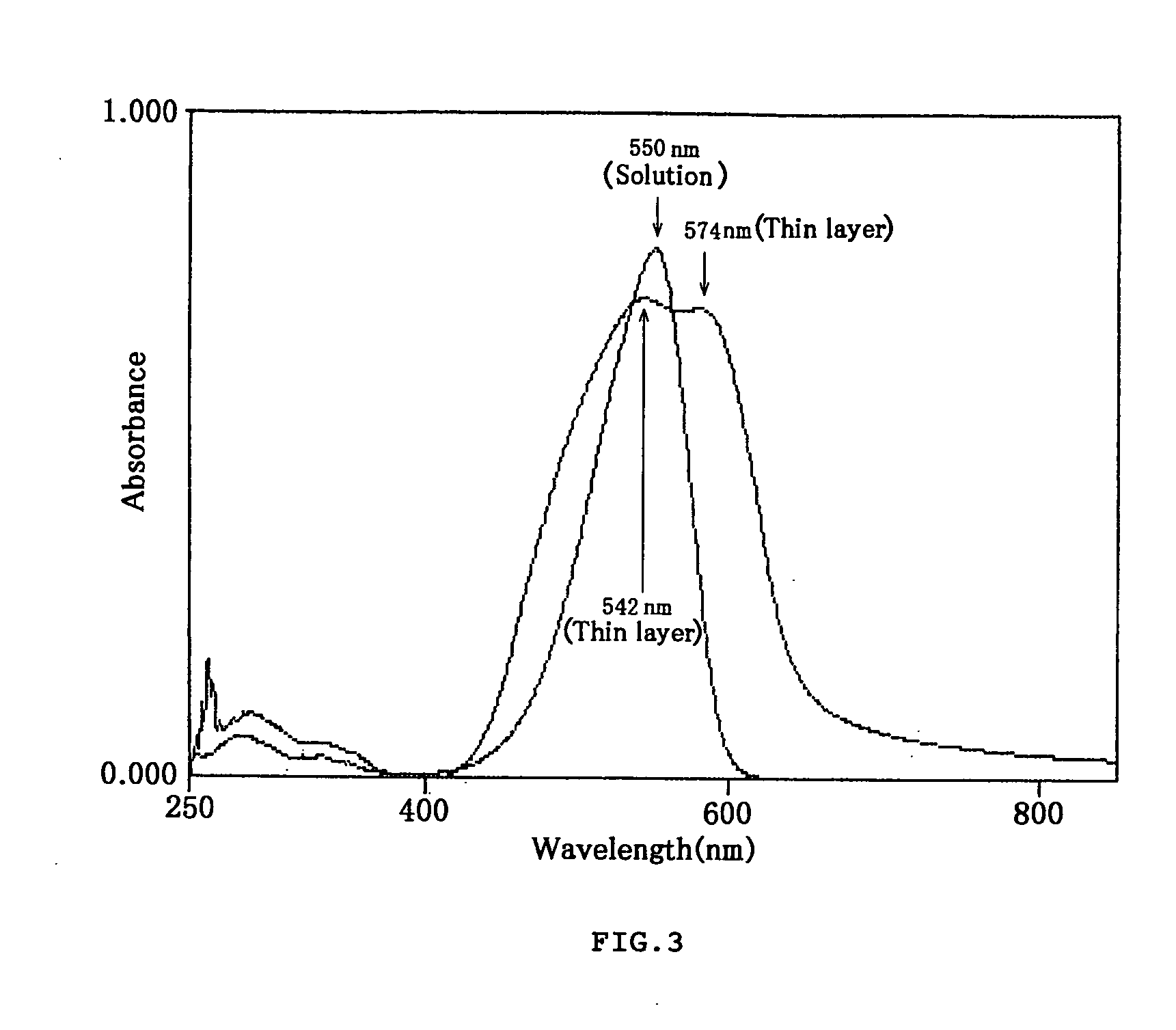
[0042] Forty milliliters of ethanol and 2 ml of triethylamine were placed in a reaction vessel, and mixed with 6 g of 1,2,3,3-tetramethyl-3H-indolenium=tosylate and 3 g of 3-nitrobenzaldehyde. The resulting mixture was reacted at 80° C. for one hour under stirring conditions, and then was cooled down. The crystals formed were collected, dissolved in a solution of methanol and chloroform under heating conditions, and then filtered. The obtained filtrate was distilled to remove chloroform and cooled to obtain 3.4 g of an orangish yellow crystal of the styryl dye represented by Chemical Formula 40. When measured in a conventional manner, the melting point of the crystal was 233° C.

[0043] The styryl dye of this Example with remarkable optical properties has various uses in many fields including those of optical recording media as a light absorbent.

example 3

Styryl Dye

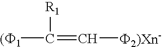
[0044] Twenty milliliters of ethanol and a very small amount of piperidine were placed in a reaction vessel, and mixed with 5 g of 1,2-dimethylquinolium=iodide and 2.2 g of 2-formylpyridine. The resulting mixture was reacted at 80° C. for 20 min under stirring conditions, and then was cooled down. The crystals formed were collected and recrystallized in ethanol to obtain 1.3 g of an orangish yellow crystal of the styryl dye represented by Chemical Formula 34. When measured in a conventional manner, the melting point of the crystal was 199-200° C.

[0045] The styryl dye of this Example with remarkable optical properties has various uses in many fields including those of optical recording media as a light absorbent.


PUM


Abstract

The present invention provides styryl dyes which have absorption maxima at a wavelength of 400 nm or less and are sensitive to a laser beam with a wavelength of 450 nm or less, light absorbents and optical recording media which comprise the styryl dyes, and a process for producing the styryl dyes which comprises reacting with an aldehyde compound a quaternary ammonium salt of nitrogen atom containing heterocyclic compound having an active methyl or active methylene group.

Description

CROSS-REFERENCE TO RELATED APPLICATIONS [0001] The present application is a divisional application of Ser. No. 09 / 890,711, filed Aug. 9, 2001, the entire contents of which is hereby incorporated by reference.FIELD OF THE INVENTION [0002] The present invention relates to organic dye compounds, and more particularly, to styryl dyes which have absorption maxima at a wavelength of 400 nm or less. BACKGROUND OF THE INVENTION [0003] In a multimedia age, optical recording media such as CD-R (a write-once memory using compact disc) and DVD-R (a write-once memory using digital video disc) are now of great importance. Most of the conventional optical recording media can be roughly classified into inorganic optical recording media which have recording layers composed of inorganic substances such as tellurium, selenium, rhodium, carbon, or carbon sulfide; and organic optical recording media which have recording layers mainly composed of light absorbents containing organic dye compounds. [0004] ...

Claims


Application Information

Patent Timeline
IPC IPC(8): C09B23/14G11B7/247
CPCC09B23/145Y10S430/146G11B7/246G11B7/2463G11B7/2467G11B7/247G11B7/2472G11B7/2475G11B7/2478G11B7/248G11B7/2495G11B7/2531G11B7/259G11B2007/24612G11B7/245
Inventor KASADA, CHIAKIKAWATA, TOSHIOYANO, KENTAROYASUI, SHIGEO
Owner KABAYUSHI KAISHI HAYASHIBARA SEIBUTSU KAGAKU KENKYUJO
Why Eureka
Try Eureka