Air conditioner

a technology for air conditioners and air conditioners, applied in the field of air conditioners, can solve the problems of increasing system complexity and cost, insufficient capacity of electric vehicle batteries, and insufficient heating capacity, and achieve the effects of preventing climate comfort from being degraded, reducing the reach time of target air-conditioning temperature, and saving spa

Inactive Publication Date: 2005-11-03
PANASONIC CORP
View PDF4 Cites 30 Cited by
  • Summary
  • Abstract
  • Description
  • Claims
  • Application Information

AI Technical Summary

Benefits of technology

[0012] In view of the above-mentioned problem, it is an object of the present invention to provide an air conditioner that achieves space saving, shortens the reach time of a target air-conditioning temperature, and prevents climate comfort from being degraded during defrosting.

Problems solved by technology

However, because the capacity of a battery of the electric vehicle is not sufficient, a hybrid electric vehicle which uses an engine for driving assist or for power generation and an electric vehicle which uses a fuel battery for power generation have been proposed.
However, two mechanisms are required: a mechanism for transmitting the rotation of an engine to the compressor and a mechanism for transmitting the rotation of a vehicle drive motor to the compressor, and also required is a clutch for switching these drive methods, increasing the system complexity and the cost.
At a low ambient temperature or the like, heating capacity was too small; therefore engine cooling water was heated with a PTC heater as an auxiliary heating means.
When an engine cooling water temperature is low at the time of heating, even if the refrigerant-to-water heat exchanger 101 is used as an auxiliary heating means, long time was required until a temperature of refrigerant passing through the refrigerant-to-water heat exchanger 101 rises high enough to start up the air conditioner; therefore there occurred a problem that it took long time for an air-conditioning temperature in a vehicle compartment to reach a target temperature, or that cool air was blown off from a heater core to the vehicle compartment inside.
Furthermore, if the evaporator 105 was frosted, defrosting operation was conducted, which caused intermittent operation, thus degrading climate pleasure.

Method used


Image

  • Air conditioner
  • Air conditioner
  • Air conditioner

Examples


embodiment 1

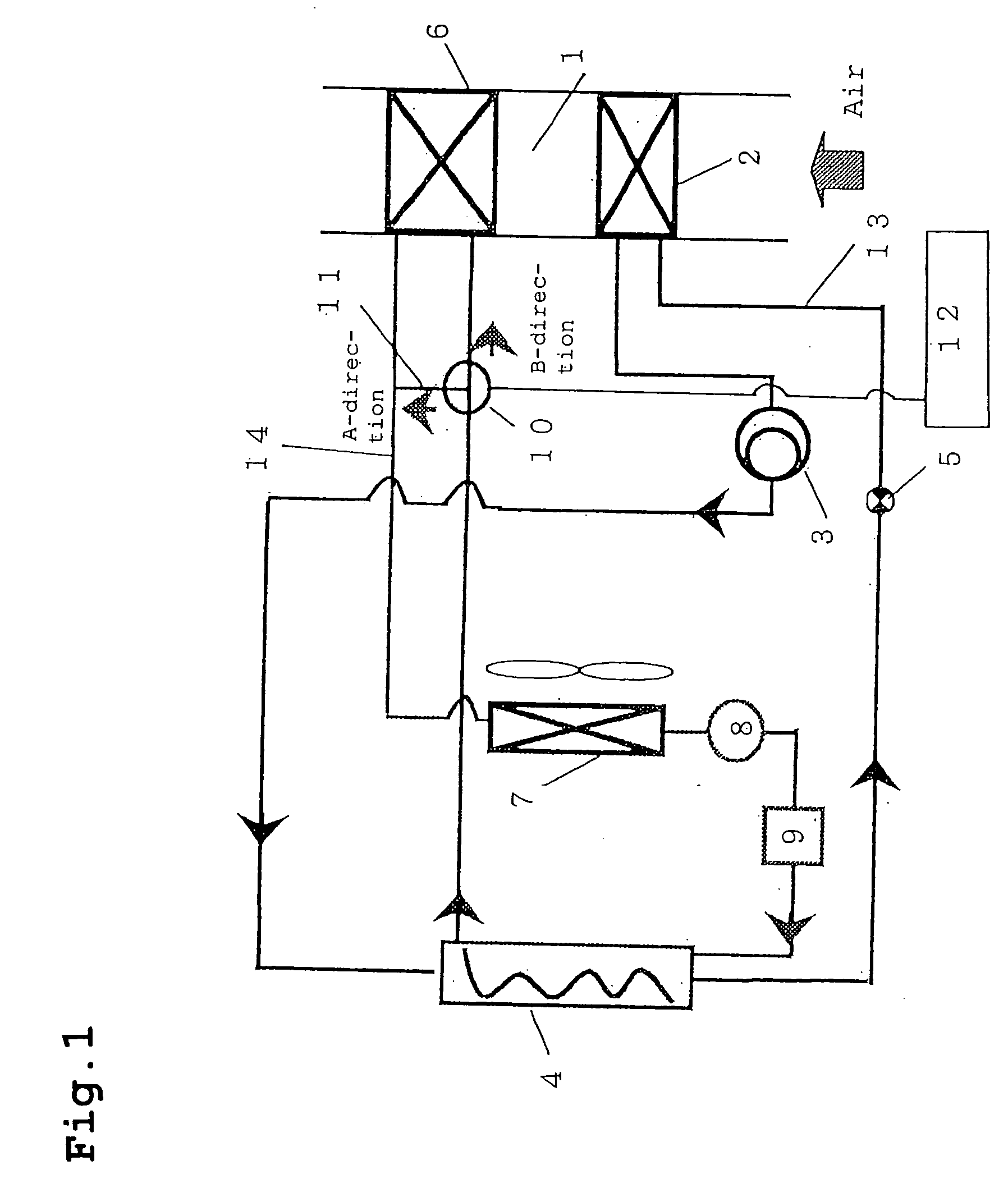
[0051]FIG. 1 is a block diagram of an air conditioner for vehicle according to an embodiment 1 of the present invention. An air conditioner for vehicle according to the embodiment 1 includes a refrigerant cycle 13, a cooling water cycle 14, and a blowing duct 1 for feeding temperature-conditioned air into a vehicle.

[0052] The refrigerant cycle 13 includes an evaporator 2 of performing air cooling by refrigerant evaporation in the blowing duct 1. A compressor 3 is installed to increase the pressure of the refrigerant evaporated by the evaporator 3. A refrigerant-to-water heat exchanger 4 is also installed to heat cooling water with the refrigerant discharged from the compressor 3. In addition, an expansion device 5 is mounted to decompress refrigerant discharged from the refrigerant-to-water heat exchanger 4 before it is fed into the evaporator 2.

[0053] The cooling water cycle 14 includes a heater core 6 installed on the downstream side of the evaporator 2 on the basis of the blast...

embodiment 2

[0067] The basic configuration of an air conditioner for vehicle according to an embodiment 2 of the present invention is the same as that of the embodiment 1 and is explained with a focus placed on differences between them. The same constituent elements as for the embodiment 1 have the same numbers on them.

[0068]FIG. 3 is a block diagram of an air conditioner for vehicle according to the embodiment 2 of the present invention.

[0069] The configuration of the refrigerant cycle 26 is the same as for the embodiment 1 and an explanation is thus omitted. The cooling cycle 27 is different from that of the embodiment 1 and does not include the three-way valve 10, the bypass 11 or the control means 12. A three-way valve 20 is installed between the power engine 9 and the pump 8. There is provided a bypass 22 connected with the three-way valve 20 as one end and a section between the power engine outlet water temperature means 21 and the refrigerant-to-water heat exchanger 4 as the other end....

embodiment 3

[0081] The basic configuration of an air conditioner for vehicle according to an embodiment 3 of the present invention is the same as that of the embodiment 2 and is explained with a focus placed on differences between them. The same constituent elements as for the embodiment 2 have the same numbers on them.

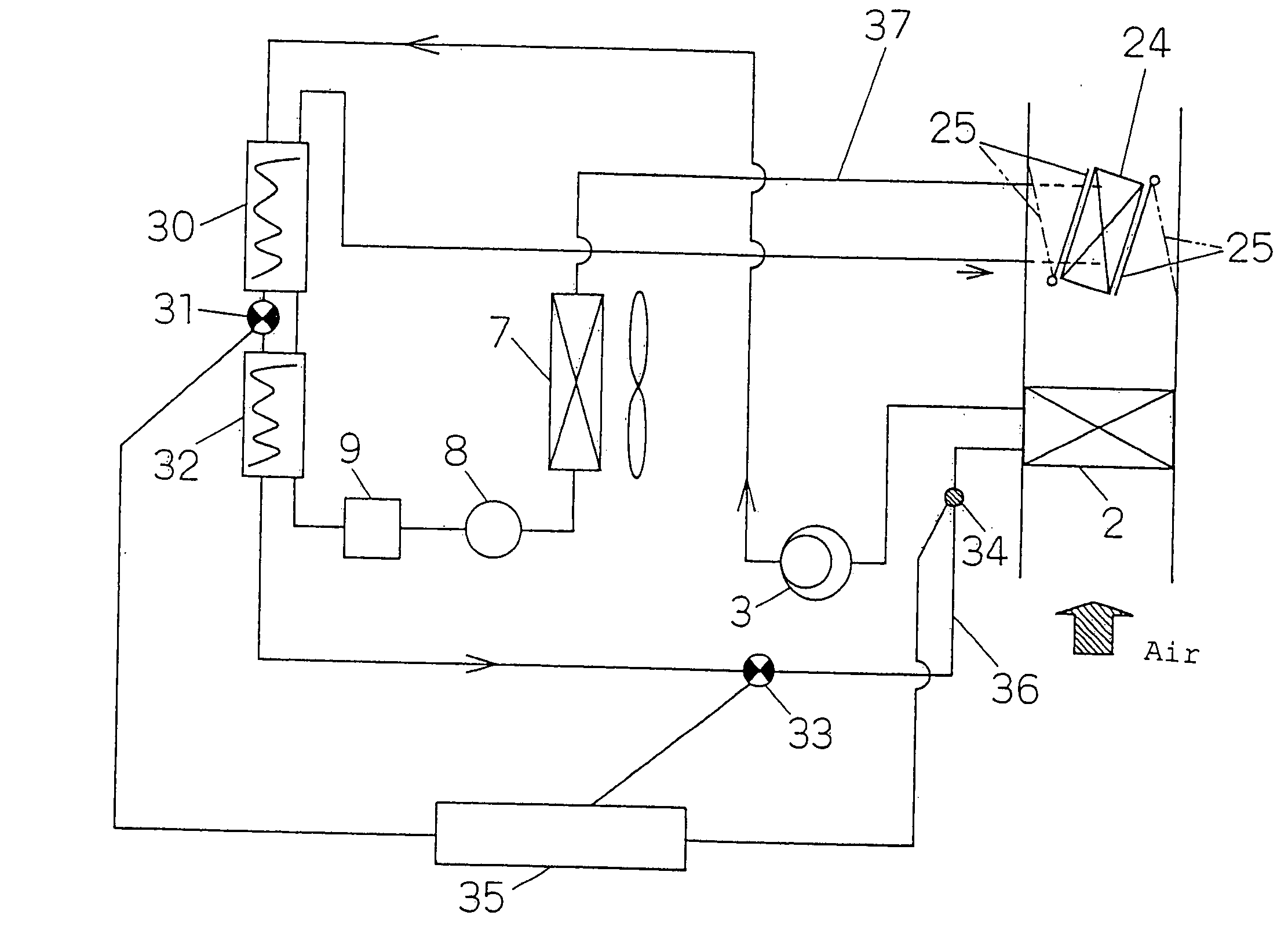
[0082]FIG. 5 is a block diagram of an air conditioner for vehicle according to the embodiment 3 of the present invention.

[0083] The refrigerant cycle 36 includes the evaporator 2 and the compressor 3 like the embodiment 2. In the embodiment 3, the first refrigerant-to-water heat exchanger 30 and the second refrigerant-to-water heat exchanger 32, and the first expansion device 31 installed between the two refrigerant-to-water heat exchangers 30, 32 are installed in place of the refrigerant heat exchanger 4 in the embodiment 2. The expansion device 12 in the embodiment 2 is corresponding to a second expansion device 33 in the embodiment 3.

[0084] Between the second expansion devi...


PUM


Abstract

An air conditioner for a vehicle includes a refrigerant cycle having an evaporator which is disposed in a blowing duct and cools air by refrigerant evaporation in the blowing duct; a compressor setting the evaporated refrigerant at a high temperature and high pressure; a refrigerant-to-water heat exchanger heating cooling water by heat transfer from the refrigerant discharged from the compressor; and an expansion device decompressing the refrigerant discharged from the refrigerant-to-water heat exchanger, The air conditioner also includes a cooling water cycle having a heater core which is disposed on the downstream side of the evaporator; a radiator cooling the cooling water; a pump circulating the cooling water cooled by the radiator; a power engine cooled by the cooling water fed by the pump; and the refrigerant-to-water heat exchanger. The refrigerant cycle performs cooling for dehumidification by performing the operation of heating.

Description

TECHNICAL FIELD [0001] The present invention relates to an air conditioner and an air conditioning method. BACKGROUND OF THE INVENTION [0002] In recent years, an electric vehicle has grown in demand from the viewpoint of global environment protection. However, because the capacity of a battery of the electric vehicle is not sufficient, a hybrid electric vehicle which uses an engine for driving assist or for power generation and an electric vehicle which uses a fuel battery for power generation have been proposed. [0003] The hybrid electric vehicle equipped with the engine for driving assist runs on a vehicle drive motor during urban driving and on the engine if a remaining battery level is low or during suburban driving. On the other hand, the hybrid electric vehicle equipped with the engine for power generation runs on a vehicle drive motor and starts an engine to charge the battery if a remaining battery level becomes low. [0004] An air conditioner for a present electric vehicle g...

Claims


Application Information

Patent Timeline
Patent Type & Authority Applications(United States)
IPC IPC(8): B60H1/00B60H1/08F25B6/04B60H1/22F25B9/00
CPCB60H1/004B60H1/00885B60H1/00899B60H2001/00928F25B2341/0662F25B9/008F25B2309/061F25B2339/047F25B6/04B60H2001/00961F25B41/39
Inventor YAKUMARU, YUUICHINISHIWAKI, FUMITOSHIOKAZA, NORIHO
Owner PANASONIC CORP
Why Eureka
Try Eureka