Optical terahertz generator / receiver

a generator/receiver and optical terahertz technology, applied in the field of optical terahertz generator/receiver, can solve the problem of quickly reabsorbing generated radiation, and achieve the effect of increasing output power and increasing emitted bandwidth

Inactive Publication Date: 2005-11-03
HAKIMI HOSAIN
View PDF13 Cites 118 Cited by
  • Summary
  • Abstract
  • Description
  • Claims
  • Application Information

AI Technical Summary

Benefits of technology

[0018] The two types of waveguide or fiber discussed above can also be made with more than one core such as a multi core structure. Each core may have the same or different materials each with different dopants embedded in them. Additionally, each core may have pump light with identical or different wavelengths resulting in single or multi-frequency terahertz radiation. The advantage of multi core structure is first, to increase the output power of the generated terahertz radiation and second, to increase the emitted bandwidth of the generated terahertz emanating from largely hollow cladding. This is important when an ultra wideband high power terahertz radiator is desired.
[0019] To generate a narrow band monochromatic coherent terahertz radiation a second light source such as a laser, in addition to the pump source, may be coupled to the core from the same or opposite end of the waveguide. The frequency of this source may be selected to coincide with frequency ωs of generated shifted photons and may be tuned under the Raman gain spectra. The reason for narrowband tendency in this case stems from the fact that only shifted photons at specific frequency ωs, residing within Δωs width, are allowed to gain power by robbing more energy from the pumping light. As a result, the shifted photons with pre-select frequency ωs grow in intensity and lead to stronger pre-select beat frequency ωtera=[ωpump−ωs] which in turn drives the oscillating dipoles at frequency ωtera more forcefully to radiate narrow band higher power terahertz wave. Indeed this embodiment that radiates narrow band coherent terahertz wave may be interpreted as a terahertz fiber or waveguide laser. Another advantage of using the second...

Problems solved by technology

However, the generated radiation may quickly be reabsorbed if surroundin...

Method used


Image

  • Optical terahertz generator / receiver
  • Optical terahertz generator / receiver
  • Optical terahertz generator / receiver

Examples


Embodiment Construction

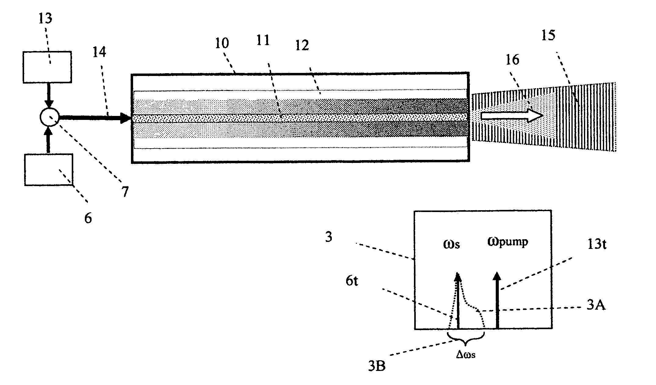
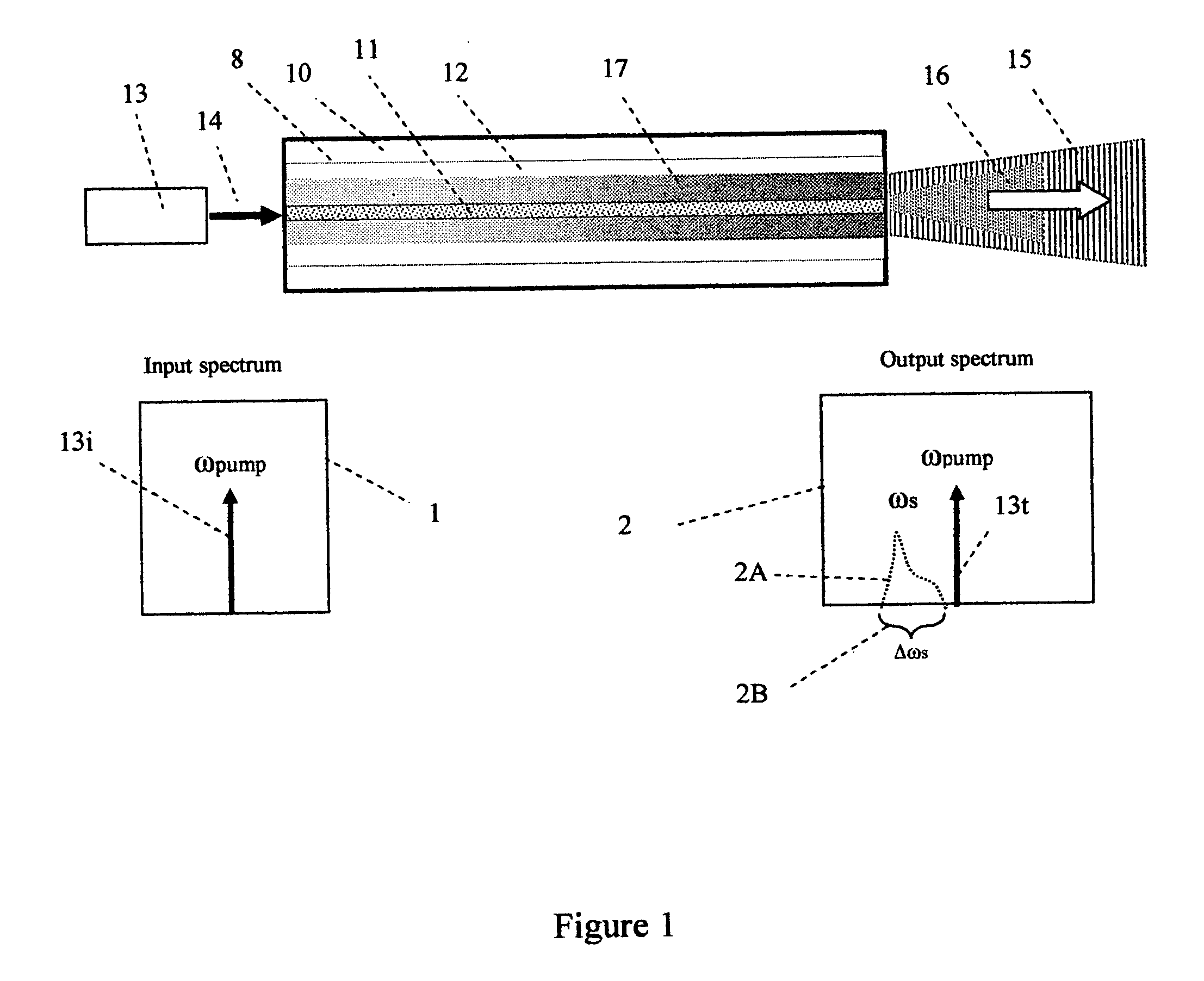
[0037]FIG. 1 constitutes the most basic terahertz wave generator. In FIG. 1, core 11 is an optical waveguide surrounded by a terahertz waveguide 12, a substantially hollow cladding or terahertz transparent region. In addition, the cladding 12 may be surrounded by substantially terahertz transparent material 10. The surface 8 surrounding cladding 12 may be reflective or transparent to terahertz radiation. Pump source 13 provides optical pumping to core 11 through optical connection 14. Source 13 may be a laser. Further, source 13 may be a tunable laser source. Optical connection 14 may be an optical fiber with a core size compatible with core 11 for optimum coupling efficiency. Alternatively connection 14 may represent a free space focused light coupled into core 11 from pump source 13. The shading 17 represent the increase in generated terahertz wave as light from source 13 is being converted to stokes shifted photons by the core medium 11. Light 16 emerging from the core 11 include...


PUM


Abstract

A method for the high power generation and detection of terahertz radiation is presented. It comprises of an optical waveguide with a core, and a mostly hollow cladding or terahertz wave transparent material surrounding the core. The cladding region is a terahertz waveguide. A pump light source is coupled to the core to promote nonlinear optical process, such as Raman scattering, in the core which in turn leads to terahertz radiation being emanated or received through fiber cladding.

Description

CROSS-REFERENCE TO RELATED APPLICATION [0001] This patent application claims the benefit of provisional patent application Ser. No. 60 / 566,351 filed 2004 Apr. 30.FEDERALLY SPONSORED RESEARCH [0002] Not applicable SEQUENCE LISTING OR PROGRAM [0003] Not applicable BACKGROUND OF THE INVENTION [0004] The invention generally relates to the generation of a coherent optical source having its center frequency in the terahertz (i.e., far infrared) band. More particularly, the present invention relates generally to generation and detection of terahertz radiation using stimulated process such as Raman scattering (SRS) in an optical waveguide such as a fiber. [0005] Terahertz (THz) radiations or T-rays represent the last bastions of relatively unexplored electromagnetic spectrum. Residing somewhere between microwave and infrared, T-rays could have frequencies anywhere from 0.1 to 20 THz. What makes T-rays special is the potential application of this radiation in many military, security, commerc...

Claims


Application Information

Patent Timeline
IPC IPC(8): G01N21/35G01T1/161
CPCG01N21/3581G02F1/353G02F2203/13
Inventor HAKIMI, HOSAIN
Owner HAKIMI HOSAIN
Why Eureka
Try Eureka