Friction welding structure for striking plate of golf club head and method therefor

a golf club head and welding structure technology, applied in the field of golf club head friction welding structure, can solve the problems of affecting the deformability hindering the transmission of the momentum of the striking plate, and it is difficult to obtain good bonding between different materials, so as to improve the bonding strength and bonding reliability of the golf club head, and widen the application area

Inactive Publication Date: 2005-11-10
FUSHENG IND CO LTD
View PDF12 Cites 28 Cited by
  • Summary
  • Abstract
  • Description
  • Claims
  • Application Information

AI Technical Summary

Benefits of technology

[0009] An object of the present invention is to provide a structure allowing the striking plate to be engaged with a body of the golf club head by friction welding, wherein th

Problems solved by technology

Although the striking effect of the golf club head is improved, it is rather difficult to obtain good bonding between different materials.
A mark exists between the engaging area between the striking plate and the body of the golf club head when insertion is adopted, which mark often hinders transmission of the momentum from the striking plate to the golf ball.
The deformability of the striking plate is adversely affected.
If the striking plate is engaged with the body of the golf club head by gluing, the bonding strength is not always satisfactory and thus could not be used with all kinds of golf club heads.
The whole golf club head must be heated if brazing is chosen, which affects the metal phase of the material of the golf club head, leading to weakening of the material and shortening of the life of the golf club head prod

Method used


Image

  • Friction welding structure for striking plate of golf club head and method therefor
  • Friction welding structure for striking plate of golf club head and method therefor
  • Friction welding structure for striking plate of golf club head and method therefor

Examples


first embodiment

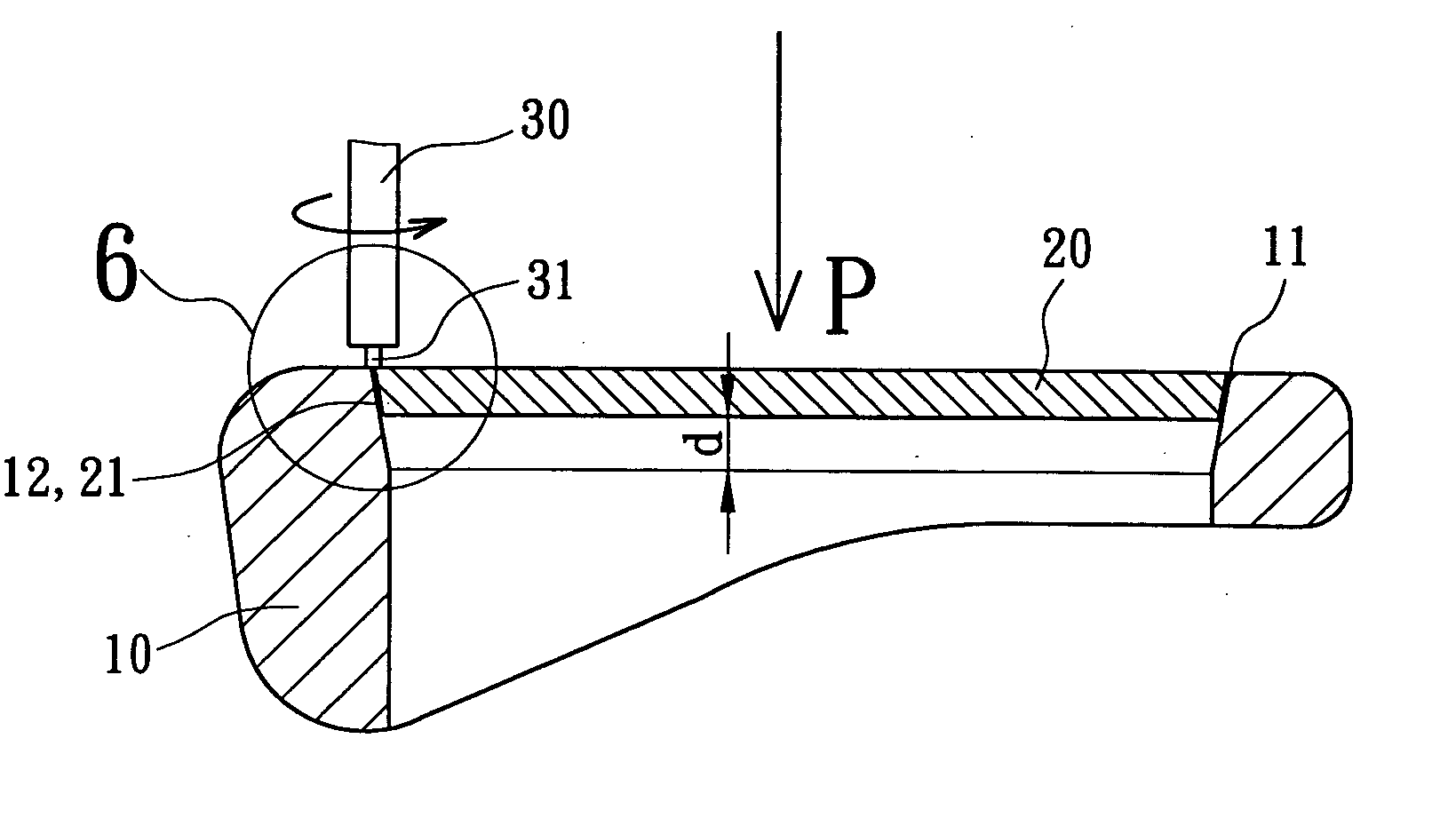
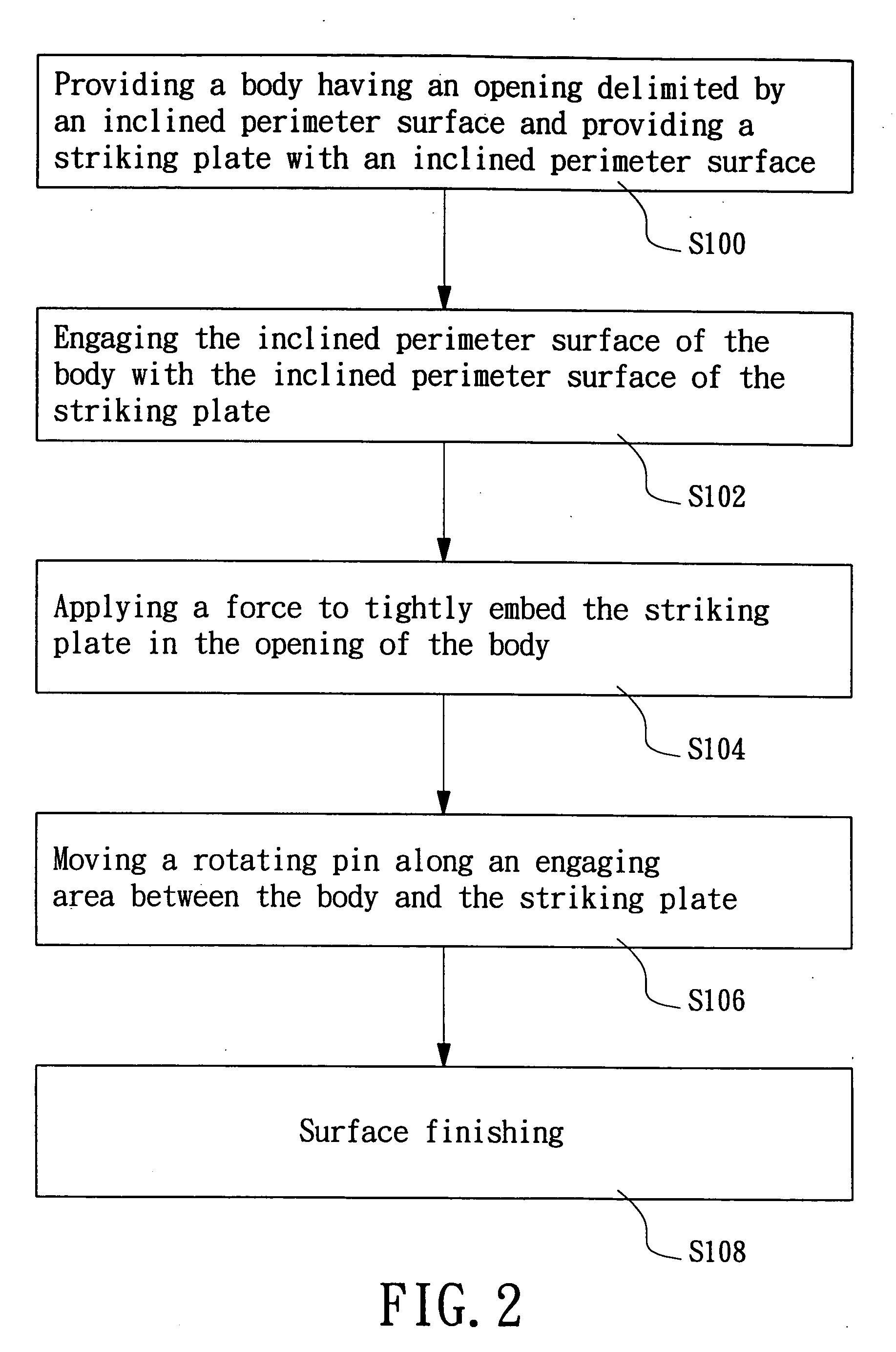
[0031] Referring to FIGS. 2 and 3, a first step of a method for manufacturing a golf club head in accordance with the present invention comprises providing a body 10 having an opening 11 delimited by an inclined perimeter surface 12 and providing a striking plate 20 with an inclined perimeter surface 21 (step S100). The golf club head is an iron club comprising a body 10 with an inclined perimeter surface 12 and a striking plate 20 with an inclined perimeter surface 21. The body 10 is made from a first material selected from the group consisting of stainless steel, titanium alloy, carbon steel, low-alloy steel, cast iron, nickel-base alloy, structural steel, Fe—Mn—Al alloy, and supper alloy.

[0032] The striking plate 20 is received in the opening 11 of the body 10. Preferably, the inclined perimeter surface 12 tapers inward and is planar or arcuate. The striking plate 20 is made from a second material selected from the group consisting of stainless steel, titanium alloy, carbon steel...

second embodiment

[0038]FIGS. 7 and 8 illustrate a second embodiment in accordance with the present invention, wherein the opening 11 of the body 10 includes a shoulder 13. Further, an intermedia layer 40 can be provided on the inclined perimeter surface 12 of the body 10 or the inclined perimeter surface 21 of the striking plate 20 by electroplating or coating. The intermedia layer 40 is formed from a material selected from the group consisting of niobium, chromium, aluminum, copper, iron, zirconium, titanium, vanadium, tantalum, silver, nickel, tungsten, and alloys thereof. Preferably, the metallurgical compatibility between the material of the body 10 and the material of the intermedia layer 40 is higher than that between the material of the body 10 and the material of the striking plate 20, and the metallurgical compatibility between the material of the striking plate 20 and the material of the intermedia layer 40 is higher than that between the material of the body 10 and the material of the str...

third embodiment

[0040]FIG. 9 illustrates the present invention, wherein an annular groove 14 is defined in the inclined perimeter surface 12 of the body 10, and an annular flange 22 is formed on the inclined perimeter surface 21 of the striking plate 20. The annular flange 22 is received in the annular groove 14 to accurately positioning the striking plate 20 in the opening 11 of the body 10. The leveling of the striking plate 20 is assured.


PUM

PropertyMeasurementUnit
Thicknessaaaaaaaaaa
Forceaaaaaaaaaa
Heightaaaaaaaaaa

Abstract

A method for manufacturing a golf club head includes providing a body having an opening delimited by an inclined surface, providing a striking plate with an inclined surface, engaging the inclined surface of the striking plate with the inclined surface of the body, applying a force to the striking plate to tightly embed the striking plate in the opening of the body, moving a rotating pin along an engaging area between the striking plate and the body to proceed with friction welding, and surface finishing the engaging area between the striking plate and the body. For carrying out the method, a friction welding structure for a golf club head includes a body having an opening delimited by an inclined perimeter surface and a striking plate having an inclined perimeter surface.

Description

BACKGROUND OF THE INVENTION [0001] 1. Field of the Invention [0002] The present invention relates to a friction welding structure for a striking plate of a golf club head and a method therefor. In particular, the present invention relates to a structure allowing the striking plate to be engaged with a body of the golf club head by friction welding. The present invention also relates to a method for frictionally welding the striking plate to the body of the golf club head. [0003] 2. Description of Related Art [0004] Current golf club heads are made of composite materials. In particular, the body and the striking plate of a golf club head are made from different materials. For example, the body can be made from 17-4PH stainless steel, and the striking plate can be made from 6A1-4V titanium alloy, thereby providing a golf club head having a body of high strength and a striking plate of excellent deformability. [0005] Although the striking effect of the golf club head is improved, it is...

Claims


Application Information

Patent Timeline
IPC IPC(8): A63B53/04B23K20/12B23K20/227B23K33/00B23P11/00
CPCA63B53/047A63B2053/0416B23K20/1225Y10T29/49945B23K20/227B23K33/004B23K20/128A63B53/0416
Inventor CHEN, CHAN-TUNG
Owner FUSHENG IND CO LTD
Why Eureka
Try Eureka