
Method of nitriding metal ring and apparatus therefor

a metal ring and nitriding technology, applied in mechanical apparatus, solid-state diffusion coatings, coatings, etc., can solve the problems of severe bending deformation of metal ring, damage to the surface of metal ring, and uneven formation of the nitrided layer above. achieve excellent hardness and toughness of metal ring

Inactive Publication Date: 2005-11-10
HONDA MOTOR CO LTD
View PDF3 Cites 11 Cited by
  • Summary
  • Abstract
  • Description
  • Claims
  • Application Information

AI Technical Summary

Benefits of technology

[0015] It is an object of the present invention to solve such an inconvenience and to provide a nitriding processing method, which enables to eliminate an oxide film from the surface of a metal ring made of maraging steel so as to activate the metal surface without damaging the surface, and which also enables to impart excellent hardness and toughness to the metal ring.

Problems solved by technology

Thus, the metal ring is exposed to severe bending deformation due to repetition of the above linear and bending states.
However, there is a problem in that when an oxide film is present on the surface of the metal ring, the above nitrided layer is not uniformly formed.
As a result, the surface of the metal ring is damaged by hydrogen fluoride, and it becomes difficult to laminate the above metal rings and to use the laminated ring for a belt for CVT.
Accordingly, if the above technique is applied to the above metal ring, it could cause a problem that the nitrided layer is formed through the full thickness of the metal ring so that it becomes difficult to maintain high toughness after formation of the nitrided layer.

Method used


Image

  • Method of nitriding metal ring and apparatus therefor
  • Method of nitriding metal ring and apparatus therefor
  • Method of nitriding metal ring and apparatus therefor

Examples


Embodiment Construction

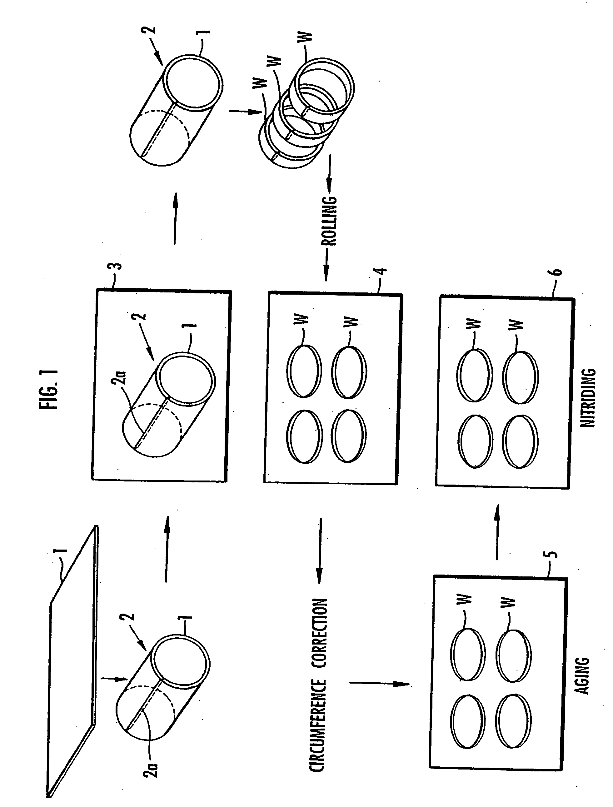
[0052] To produce the above metal ring, first, as shown in FIG. 1, a thin plate 1 made of maraging steel is bended in a loop, and one edge of the plate is welded to the other edge, so as to form a cylindrical drum 2. The above maraging steel is low-carbon steel comprising 0.03% or less C, 0.10% or less Si, 0.10% or less Mn, 0.01% or less P, and 0.01% or less S. It is what is called 18% Ni steel comprising 18% to 19% Ni, 4.7% to 5.2% Mo, 0.05% to 0.15% Al, 0.50% to 0.70% Ti, and 8.5% to 9.5% Co. Since the above maraging steel shows age hardening by the heat of welding, both sides of the welded portion 2a of the drum 2 become hardened.

[0053] Hence, the drum 2 is then placed in a vacuum furnace 3 and maintained at a temperature of 820° C. to 830° C. for 20 to 60 minutes, so that the first solution treatment is carried out and uneven hardness is eliminated. After completion of the above first solution treatment, the drum 2 is carried away from the vacuum furnace 3, and it is cut to a c...


PUM

PropertyMeasurementUnit
Temperatureaaaaaaaaaa

Abstract

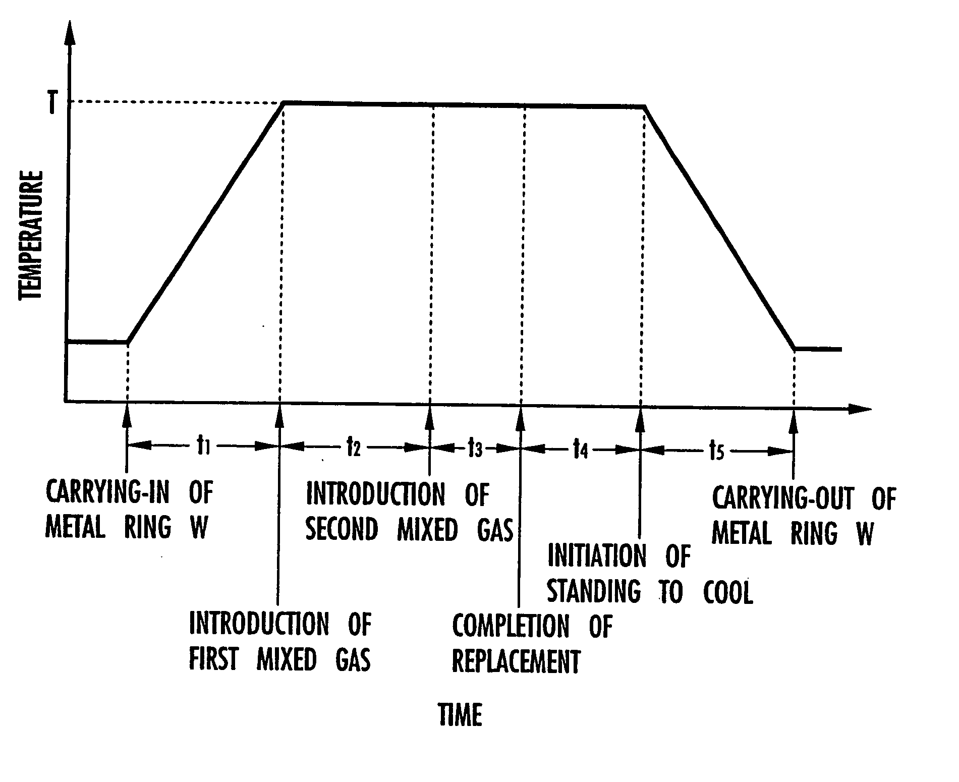
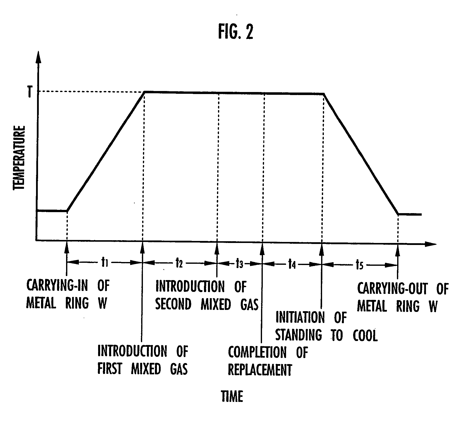
A metal ring made of maraging steel is heated in the presence of a halogen compound gas, so as to eliminate an oxide film from the surface of the metal ring and to form a halogenous compound film. Thereafter, the metal ring is heated under a vacuum or reduced pressure atmosphere to eliminate the halogenous compound film, and then it is maintained under an atmosphere comprising ammonia at a processing temperature ranging between 450° C. and 500° C. for a processing time ranging between 30 and 120 minutes, so as to carry out a nitriding processing. The above nitriding processing comprises the steps of: placing the above metal ring into a heating furnace and raising the temperature inside the heating furnace to the above processing temperature; introducing a first mixed gas consisting of 50% to 90% ammonia byvolume, 0.1% to 0.9% oxygen by volume, and a residual volume consisting of nitrogen into the heating furnace, and maintaining the above processing temperature, so as to form a nitrided layer on the surface of the metal ring; and when the one-third to one-half of the processing time has passed, replacing the atmosphere inside the heating furnace by a second mixed gas consisting of 0% to 25% ammonia by volume and a residual volume consisting of nitrogen, and maintaining the above processing temperature until the remaining processing time passes.

Description

TECHNICAL FIELD [0001] The present invention relates to a method of nitriding a metal ring made of maraging steel, which is used for a belt for continuously variable transmission and the like, and an apparatus therefor. BACKGROUND ART [0002] There is known a belt for CVT, which is obtained by laminating multiple metal rings to form a laminated ring and combining the laminated ring with a certain shaped element. It is conventionally used for power transmission of continuously variable transmission (CVT) of an automobile or the like. [0003] A metal ring forming the above laminated ring consists of low-carbon steel comprising Ni and Mo, such as maraging steel. The metal ring is produced, for example, by cutting a thin plate of the above low-carbon steel into a rectangle, rounding the thin plate along the long side, welding one edge on the short side to the other edge on the other short side to form a cylindrical drum, and cutting the drum to a certain width, so as to obtain an endless ...

Claims


Application Information

Patent Timeline
IPC IPC(8): C23C8/02C23C8/26F16G5/16
CPCC23C8/02C23G5/00F16G5/16C23C8/26
Inventor SUZUKI, TEIJISARUYAMA, MASAOMITAKAGAKI, MASASHINARITA, NAOKI
Owner HONDA MOTOR CO LTD
Learn More