Single-layer polishing pad and method of producing the same

Active Publication Date: 2005-11-10
IV TECH CO LTD
View PDF13 Cites 12 Cited by
  • Summary
  • Abstract
  • Description
  • Claims
  • Application Information

AI Technical Summary

Benefits of technology

[0021] In the foregoing, a pore-size-distribution property in a porous polymer is utilized to produce a single-layer polishing pad having two surfaces with uniform rigidity or vario

Problems solved by technology

Limited by the focus depth of an exposing machine, pattern transferal from a photomask to a photoresist layer is increasingly difficult, and the exposed pattern of the photoresist layer is increasingly distorted.
The CMP process thus suffers from low throughput.
As stated in U.S. Pat. No. 6,217,426, although a composite polishing pad can partially satisfy both the planarity and the uniformity requirements of the CMP process, some other problems are also produced.
For example, pressure transmission is different for a rigid pad and a soft pad, and the polishing

Method used


Image

  • Single-layer polishing pad and method of producing the same
  • Single-layer polishing pad and method of producing the same
  • Single-layer polishing pad and method of producing the same

Examples


Example

Embodiment 1

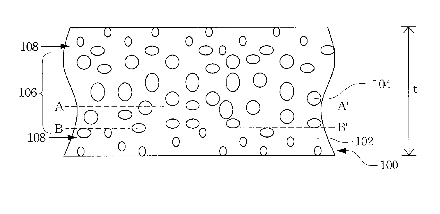
[0034] According to a preferred embodiment, a polishing pad is formed by the foam process described above. Reference is made to FIG. 1; the polymer 102 of the foamed polymer 100 is preferably polyurethane, epoxy resin, phenol formaldehyde resin, melamine resin or other suitable thermosetting resins. The foamed polymer 100 can be made by any suitable foam process, such as injection molding. The material of the polymer 102 and the porosity of the foamed polymer 100 can affect the rigidity of the foamed polymer 100. Since any one skilled in the art can adjust the relevant factors affecting the rigidity of the foamed polymer 100, a detailed discussion of the same is omitted here.

[0035] The ratio of the porosity of the interior region 106 (Pi) over the porosity of the surface region (Ps), i.e. Pi / Ps, is preferably larger than 1.3, and more preferably greater than 1.5. The thickness of the foamed polymer 100 is preferably about 2 mm to about 8 mm.
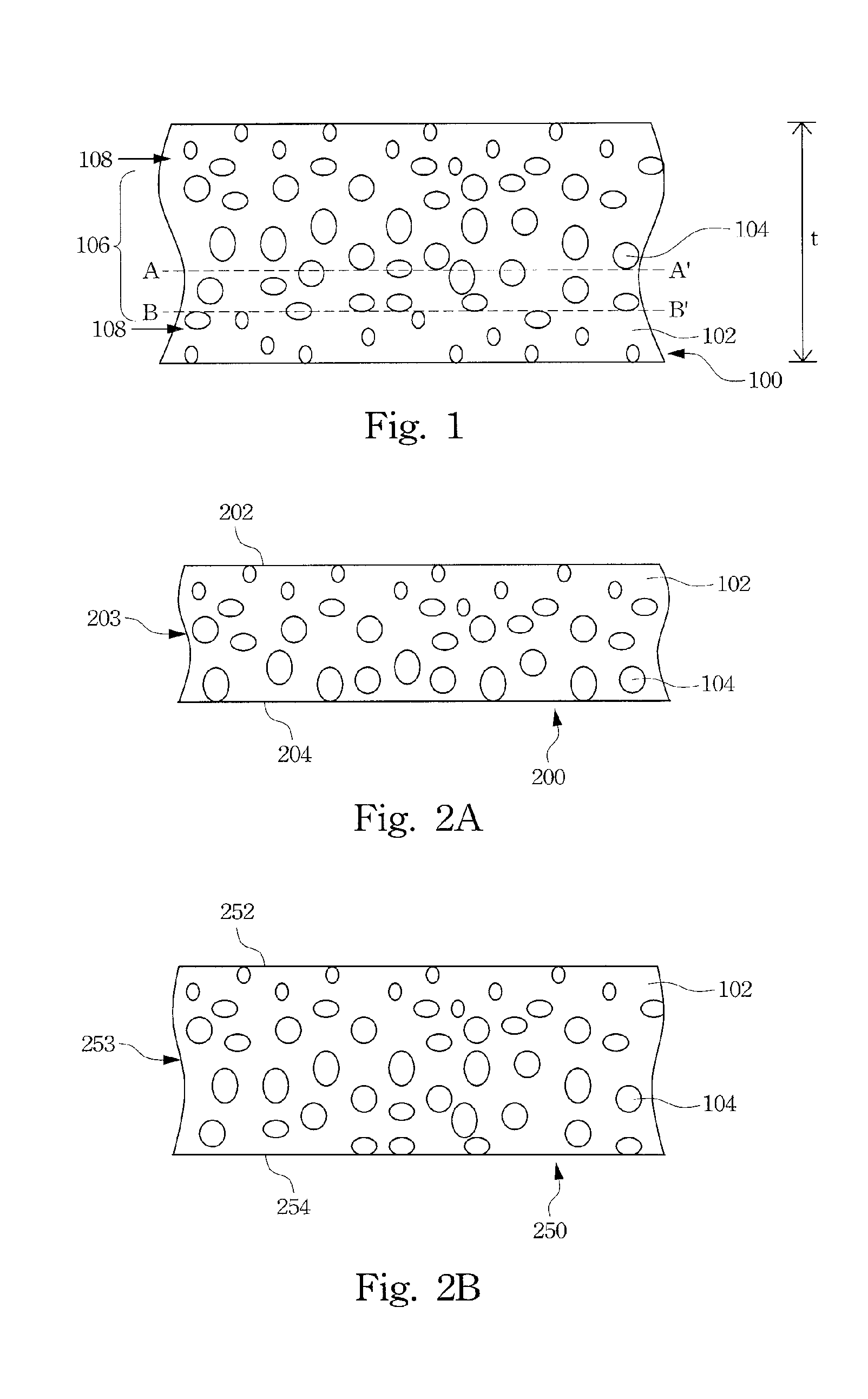
[0036] Therefore, a suitabl...

Example

Embodiment 2

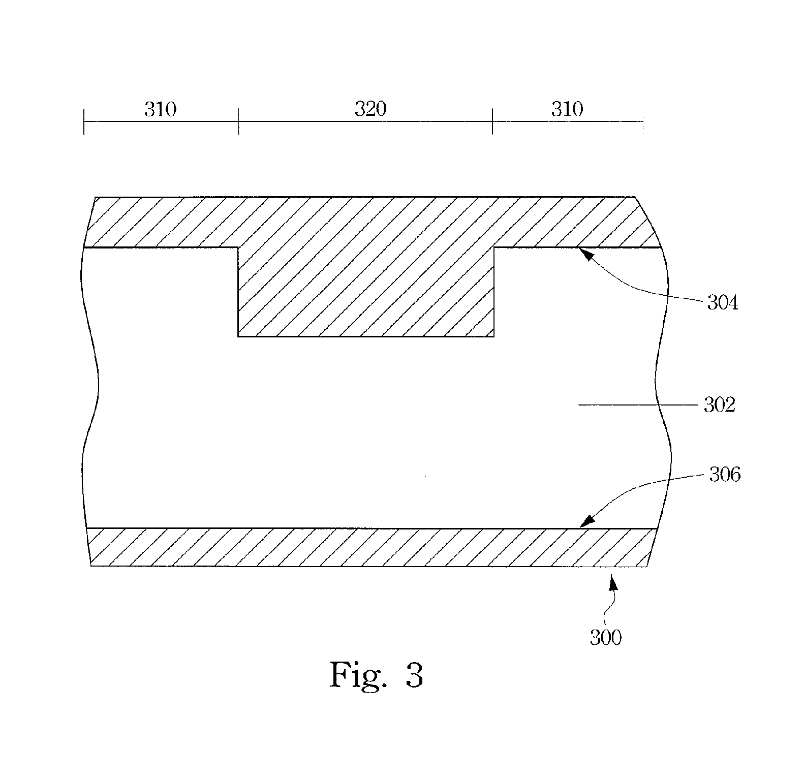
[0040] According to another embodiment, a mold, as shown in FIG. 3, can be used to produce a desired polishing pad by a foam process. FIG. 3 is a cross-sectional diagram showing a mold according to a second preferred embodiment of this invention. In FIG. 3, the mold 300 has a cavity 302, the interior bottom surface 306 is planar, and the interior top surface 304 is non-planar. Hence, the cavity 302 can be divided into at least two regions having different spacing. That is, a region 310 has a larger spacing and a region 320 has a smaller spacing.

[0041] For example, a polymer is injected into the mold cavity 302 of the mold 300 in an injection molding process with a foaming agent, a gas, or a combination thereof added. The polymer is foamed in the cavity 302 of the mold 300 to form a foamed polymer 400, as shown in FIG. 4. FIG. 4 is a cross-sectional diagram showing a foamed polymer formed by using the mold shown in FIG. 3. The polymer 401 of the foamed polymer 400 is pr...


PUM

PropertyMeasurementUnit
Thicknessaaaaaaaaaa
Densityaaaaaaaaaa
Shapeaaaaaaaaaa

Abstract

A foamed plastic is cut to form a single-layer polishing pad having a desired rigidity and compressibility. A polishing surface of the polishing pad has a higher density than a mounting surface of the polishing pad. The polishing surface and the mounting surface may have different areas having different densities for achieving desired rigidity and compressibility property. Furthermore, methods of making such single-layer polishing pads are also disclosed.

Description

CROSS-REFERENCE TO RELATED APPLICATIONS [0001] This application claims the priority benefit of U.S. Provisional Application Ser. No. 60 / 521,483, filed May 5, 2004, and U.S. Provisional Application Ser. No. 60 / 521,740, filed Jun. 29, 2004, the full disclosures of which are incorporated herein by reference.BACKGROUND [0002] 1. Field of Invention [0003] The present invention relates to a polishing apparatus and manufacturing method thereof. More particularly, the present invention relates to a single-layer polishing pad and a method of producing the same. [0004] 2. Description of Related Art [0005] During the manufacturing process of semiconductor integrated circuits, isolation structures, metal lines and dielectric layers are stacked layer by layer, and the surface of a wafer is thus less and less planar. Limited by the focus depth of an exposing machine, pattern transferal from a photomask to a photoresist layer is increasingly difficult, and the exposed pattern of the photoresist la...

Claims


Application Information

Patent Timeline
IPC IPC(8): B24B1/00B24B37/04B24D11/00B24D13/14
CPCB24B37/24B24D11/001B24D3/32
Inventor SHIH, WEN-CHANGCHANG, YUNG-CHUNGCHU, MIN-KUEI
Owner IV TECH CO LTD
Why Eureka
Try Eureka