Power source device and charge controlling method to be used in same

a technology of power source device and charge control method, which is applied in secondary cell servicing/maintenance, instruments, batteries, etc., can solve the problems of unstable power generated by solar cells, degraded reference voltage accuracy, and not being able to achieve the optimal operating point of solar cells, etc., and achieve high efficiency

Active Publication Date: 2005-11-17
NEC ENERGY DEVICES LTD
View PDF1 Cites 62 Cited by
  • Summary
  • Abstract
  • Description
  • Claims
  • Application Information

AI Technical Summary

Benefits of technology

[0009] In view of the above, it is an object of the present invention to provide a power source device which is capable of charging a secondary cell in a stable manner even in a state in which power generated by a solar cell varies due to changes in intensity of sunlight (solar irradiation) and / or in ambient temperature, and also capable of charging a secondary cell with high efficiency without being affected by impedance of the secondary cell and wirings.

Problems solved by technology

However, the conventional power source device presents a problem in that power to be generated by the solar cell is not stable due to changes in the surrounding environments such as variations in intensity of sunlight (solar irradiation) and in ambient temperatures.
However, the above conventional power source device has the following problems.
That is, for example, in the above conventional power source device, if the solar cell is mounted in a place being far from the power source device, since a circuit to produce the reference voltage is separated from the power source device, an electric wiring between the circuit to produce the reference voltage and the power source device is made long and as a result, appearance of electric noises and a voltage drop caused by wiring resistance occur, which cause accuracy of the reference voltage to be degraded and the operating point of the solar cell not to be at the optimum value.
Another problem is that, if the battery, having a single-piece construction such that the solar cell and the power source device are integrated together, is placed outdoors, a temperature of the battery exceeds its upper limit in a use temperature range, in a high temperature environment, for example, in a state of mid-summer with no breeze and, as a result, there is a risk that the battery produces heat or breakdown.
Moreover, in the case of constant-current charging in a low temperature environment, there is a possibility that charging efficiency decreases due to an increase in internal impedance of the battery itself.
Furthermore, even when only the battery is put indoors to moderate temperature environments, there is a possibility that a decrease in efficiency in the constant-current charging occurs due to an increase in resistance of wirings to connect the battery to the power source device.
There is still another problem in that, when electric power generated by the solar cell is low in such a state in which the intensity of sunlight is low in the morning or the evening, on a cloudy day, or a like, a long time is required to increase a charging voltage up to the most suitable operating point due to a leak current in the electric double-layer capacitor or to power consumed in a static state in internal circuits of the power source device and a period required to put the switching device in an ON state is made long, which causes the charging efficiency to be degraded.

Method used


Image

  • Power source device and charge controlling method to be used in same
  • Power source device and charge controlling method to be used in same
  • Power source device and charge controlling method to be used in same

Examples


first embodiment

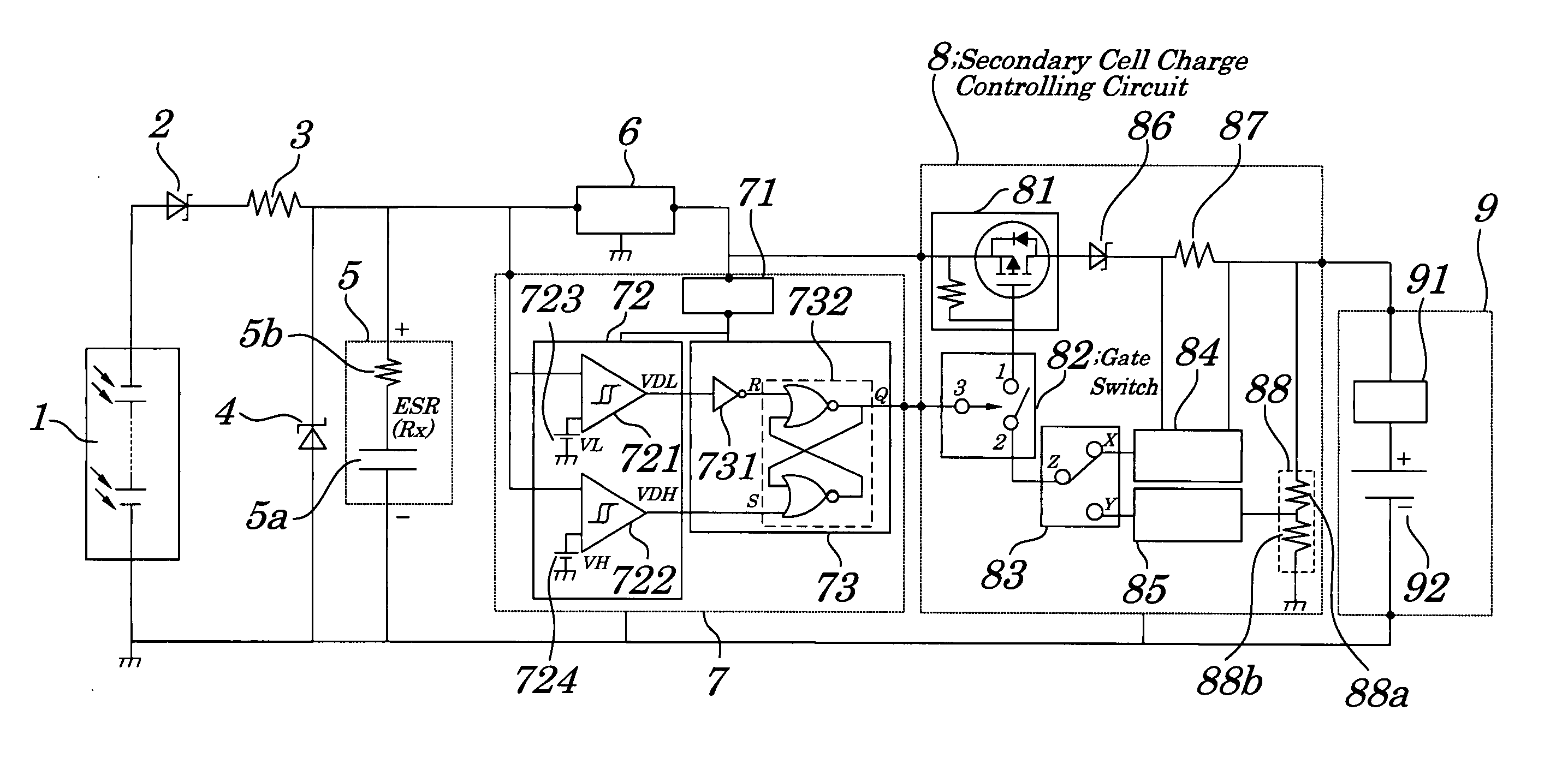
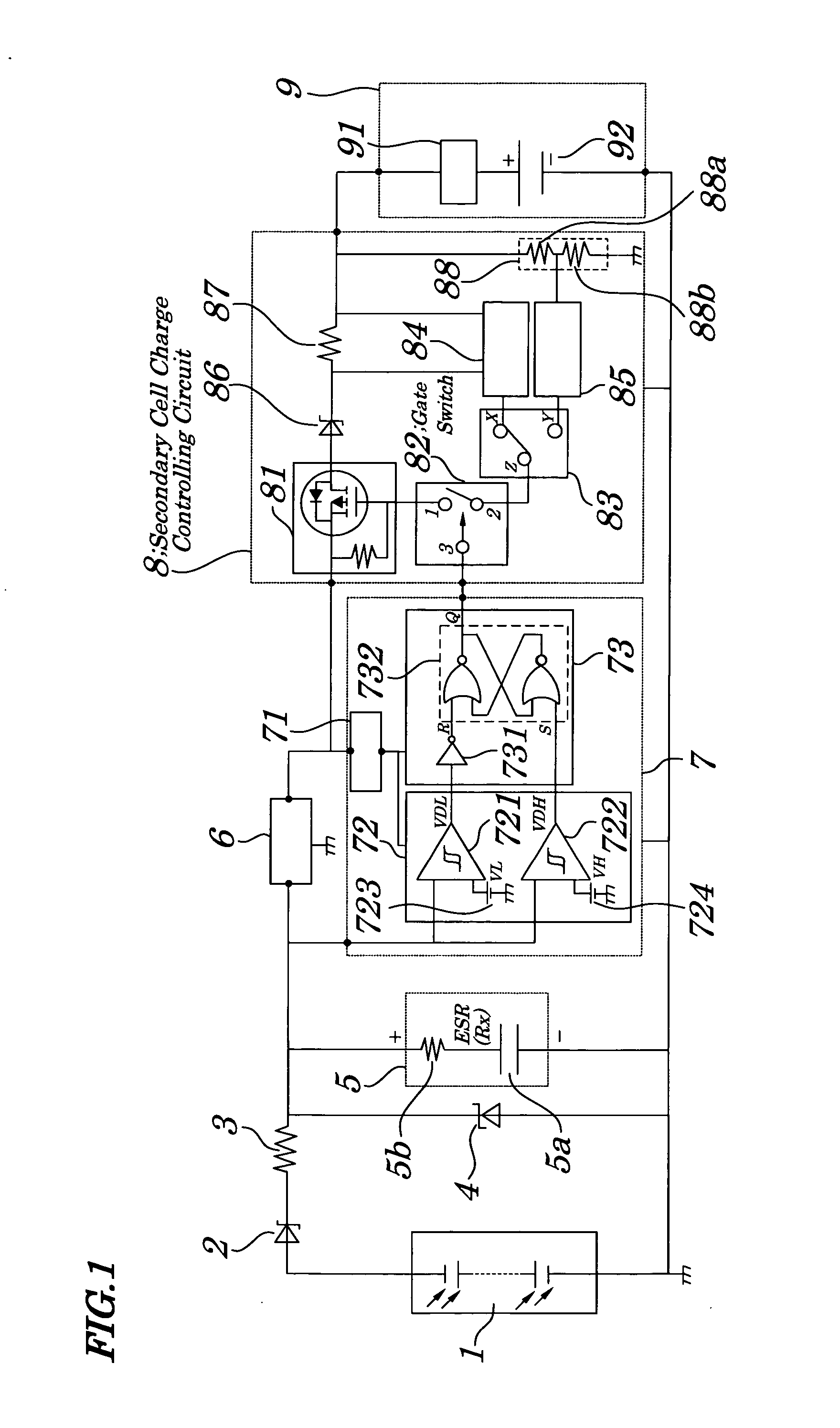
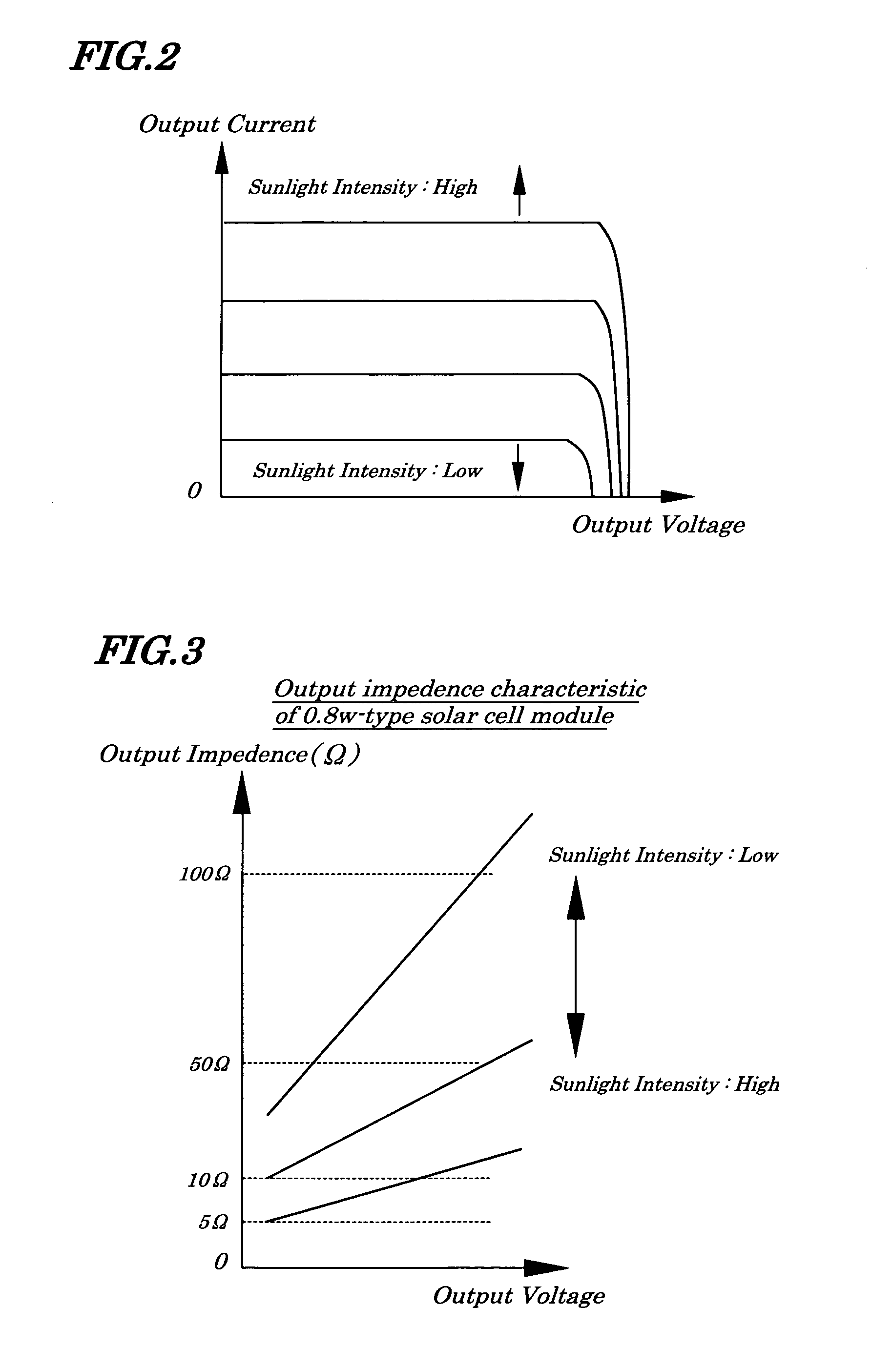
[0057]FIG. 1 is a circuit diagram illustrating electrical configurations of a power source device of a first embodiment of the present invention. The power source device, as shown in FIG. 1, includes a solar cell module 1, a first reverse-current preventing element (device) 2, a current limiting element 3, an overvoltage protecting element (device) 4, an electric double-layer capacitor 5, a booster-type DC (Direct Current)-DC converter 6, a charge on / off controlling circuit 7, a secondary cell charge controlling circuit 8, and a secondary cell pack 9. The solar cell module 1 is made up of a plurality of solar cells being connected (placed) in series and / or in parallel to directly convert sun energy into electrical energy. In the embodiment in particular, the solar cell module 1 is constructed by combining solar cells formed on a substrate made of a silicon semiconductor or a compound semiconductor being arranged in a planar manner and has an output characteristic as shown in FIG. 2,...

second embodiment

[0093]FIG. 11 is a circuit diagram showing electric configurations of a power source device of a second embodiment of the present invention. In FIG. 11, same reference numbers are assigned to components having the same functions as those in FIG. 1. In the power source device of the second embodiment, an output converter 10 is mounted in a back-stage in a secondary cell pack 9 in FIG. 11. The output converter 10 is made up of a DC-DC converter 101 and a DC-DC converter 102. Input terminals of the DC-DC converters 101, 102 are commonly connected to a positive polarity terminal of the secondary cell pack 9. An output A of the DC-DC converter 101 is connected to a load L1; and an output B of the DC-DC converter 102 is connected to a load L2. Other configurations of the components have the same configurations as those in FIG. 1.

[0094] In the power source device of the second embodiment, as in the case of the first embodiment, electric energy converted from sun energy by the solar cell m...

third embodiment

[0095]FIG. 12 is a circuit diagram showing electrical configurations of the power source device of a third embodiment of the present invention. In FIG. 12, same reference numbers are assigned to components having the same function as those in FIG. 1. The power source device of the third embodiment includes a solar cell module 1, a first reverse-current preventing element 2, a current limiting element 3, a booster-type DC / DC converter 6, a charge on / off controlling circuit 7, a secondary cell charge controlling circuit 8, a secondary cell pack 9, a main capacitor 11, a sub-capacitor 12, a main capacitor overvoltage protecting element 13 (device), a sub-capacitor overvoltage protecting element (device) 14, a main capacitor reverse-current preventing element 15, a sub-capacitor reverse-current preventing element (device) (device) 16, a charging capacitor selecting circuit 17, a capacitor charging voltage comparing circuit 18, and a sub-capacitor discharge controlling circuit 19. The ma...


PUM

PropertyMeasurementUnit
output impedanceaaaaaaaaaa
withstand voltageaaaaaaaaaa
impedanceaaaaaaaaaa

Abstract

A power source device is provided which is capable of charging a secondary cell in a stable manner even in an environment in which power generated by a solar cell varies due to changes in sunlight intensity and/or ambient temperatures. By power generated by a solar cell module, an electric double-layer capacitor is charged and, by using a charging voltage of the electric double-layer capacitor, a booster-type DC-DC (Direct Current-Direct Current) converter is driven. A charge on/off controlling circuit detects the voltage of the electric double-layer capacitor and, when the voltage exceeds a high level threshold voltage, keeps a charge controlling signal (output signal from a terminal) in an active mode and performs a charge starting operation and, after that, when the voltage of the electric double-layer capacitor reaches a low level threshold value, holds the charge controlling signal in a non-active mode and performs a charge stopping operation.

Description

BACKGROUND OF THE INVENTION [0001] 1. Field of the Invention [0002] The present invention relates to a power source device and a charge controlling method to be used in the power source device, and more particularly to the power source device in which electric power generated by a solar cell is temporarily stored in an electric double-layer capacitor and which has a secondary cell to be charged based upon the electric power stored in the electric double-layer capacitor and which is suitably used, for example, even in a place where power infrastructure is not provided, and to the charge controlling method to be used in the above power source device. [0003] The present application claims priority of Japanese Patent Application No. 2004-145705 filed on May 14, 2004, which is hereby incorporated by reference. [0004] 2. Description of the Related Art [0005] A power source device having a secondary cell to be charged by a solar cell that converts solar light energy into electricity is bei...

Claims


Application Information

Patent Timeline
Patent Type & Authority Applications(United States)
IPC IPC(8): H01L31/00H02J7/35H01L31/058H01M10/44H02J7/00H02M3/155
CPCH02J7/35H02S40/38Y10S136/293Y02E10/566Y02E10/56Y02E70/30H02J7/00
Inventor SASAKI, HIROSHI
Owner NEC ENERGY DEVICES LTD
Why Eureka
Try Eureka