Nano-calorimeter device and associated methods of fabrication and use

US20050254547A1Inactive Publication Date: 2005-11-17GENERAL ELECTRIC CO

Image

  • Nano-calorimeter device and associated methods of fabrication and use
  • Nano-calorimeter device and associated methods of fabrication and use
  • Nano-calorimeter device and associated methods of fabrication and use

Examples


Embodiment Construction

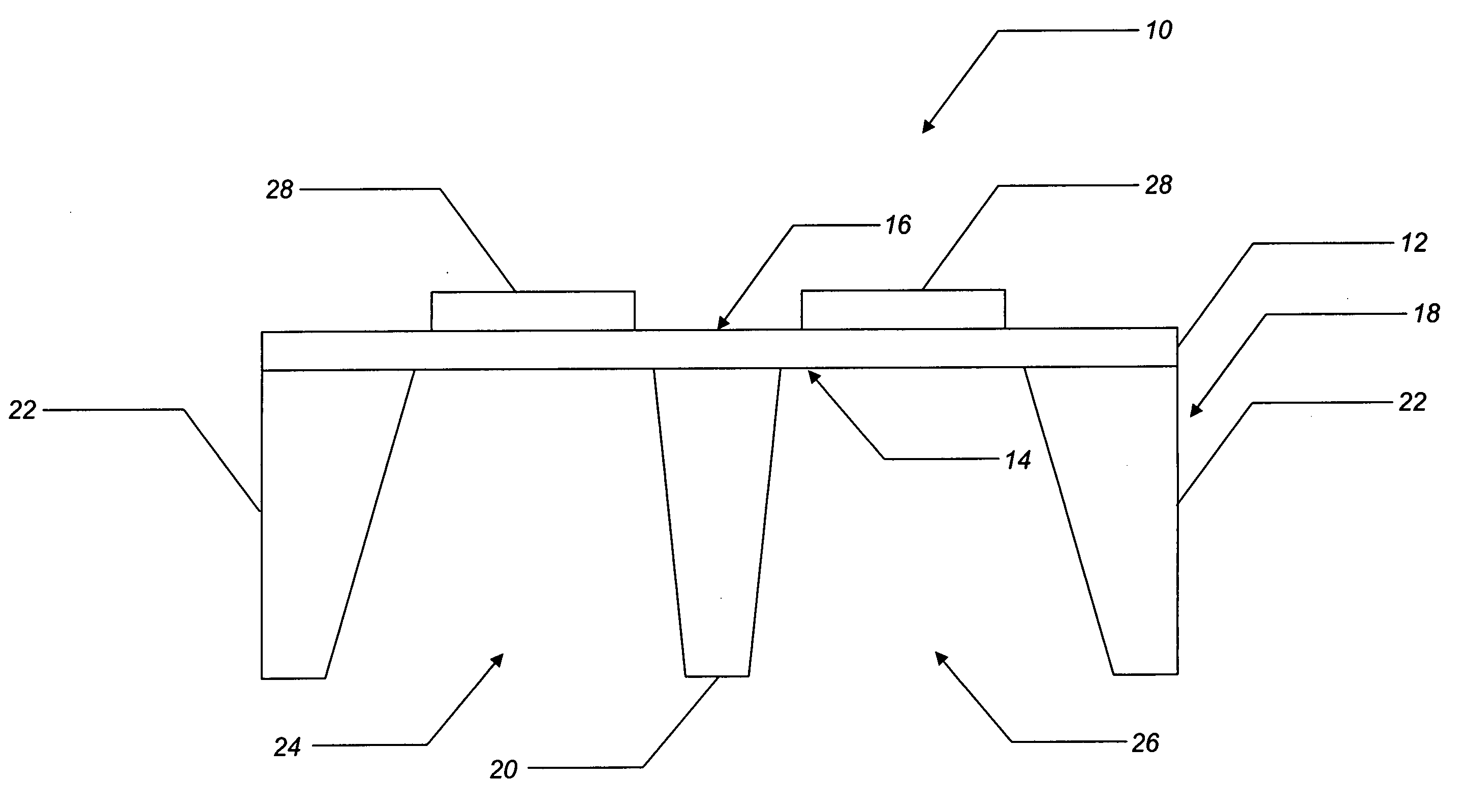
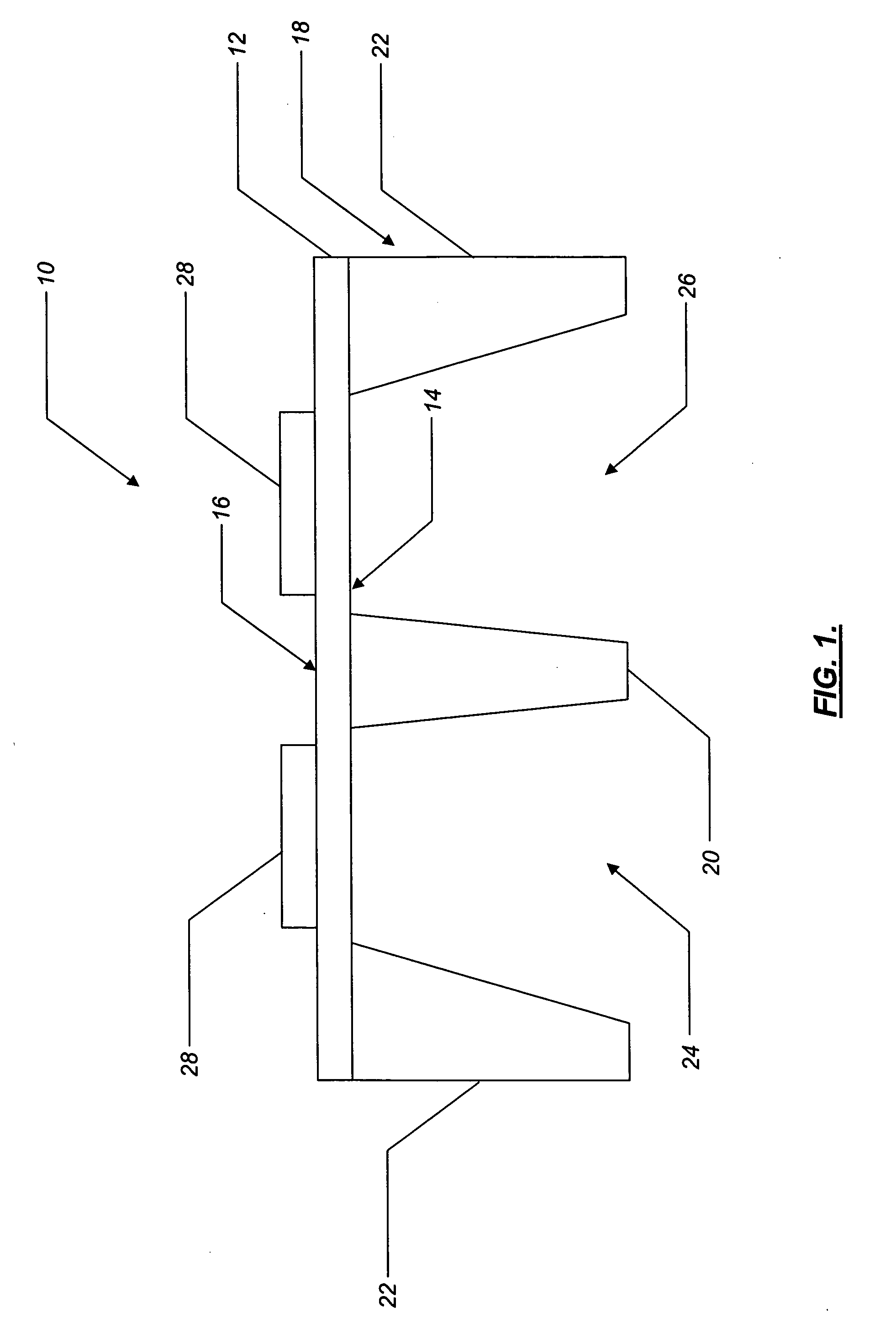
[0025] Referring to FIG. 1, in one embodiment, the nano-calorimeter device of the present invention includes one or more twin-cell differential sensors 10, each of the twin-cell differential sensors 10 comprising a chip transducer that is operable for measuring heat flow. Each of the twin-cell differential sensors 10 includes a membrane 12 that has a relatively low heat capacity and thermal conductivity, such as a free-standing thin film silicon nitride (SiNx) membrane, a polymeric membrane, or the like. Si3N, or the like may also be used. The membrane 12 has a first surface 14 and a second surface 16, and a thickness of between about 20 nm and about 5000 nm, preferably between about 30 nm and about 100 nn. The membrane 12 has a width of between about 100 nm and about 10 mm, preferably about 2 mm, and a length of between about 100 nm and about 10 mm, preferably about 5 mm. Optionally, a thermally-insulating dielectric layer 90 (FIG. 8) (SiO2, air, etc.) is disposed adjacent to and i...


PUM


Abstract

The present invention provides a nano-calorimeter device operable for measuring and characterizing the thermodynamic and other physical properties of materials that are confined to essentially nano-scale dimensions. The nano-calorimeter device including a thin film membrane having a first surface and a second surface. The nano-calorimeter device also including a frame structure disposed adjacent to and in thermal contact with the first surface of the thin film membrane, the frame structure defining a plurality of hollow cells adjacent to and in thermal contact with the first surface of the thin film membrane. The nano-calorimeter device further including one or more micro-heating elements disposed adjacent to and in thermal contact with the second surface of the thin film membrane, the location of the one or more micro-heating elements disposed adjacent to the second surface of the thin film membrane substantially corresponding to the location of the plurality of hollow cells defined adjacent to the first surface of the thin film membrane.

Description

FIELD OF THE INVENTION [0001] The present invention relates generally to the fields of nano-technology and differential scanning calorimetry. More specifically, the present invention relates to a near-adiabatic nano-calorimeter device and associated methods of fabrication and use. The nano-calorimeter device of the present invention is used to measure and characterize the thermodynamic and other physical properties of materials that are confined to essentially nano-scale dimensions. BACKGROUND OF THE INVENTION [0002] The thermodynamic and other physical properties of materials that are confined to essentially nano-scale dimensions, such as organic (polymeric and biological) and inorganic ultra-thin (essentially two-dimensional or surface) films and nano-particles, differ significantly from those of bulk (essentially three-dimensional) materials. For example, organic ultra-thin films and nano-particles typically have heat capacities that are relatively smaller and demonstrate thermal...

Claims


Application Information

Patent Timeline
17 Nov 2005
Publication
US20050254547A1
IPC
G01K17/00; G01N25/00; G01N25/20; G01N25/48
CPC
B82Y15/00; G01N25/4866; G01K17/006
Inventors
ZRIBI, ANIS; ALIZADEH, AZAR