Artificial spinal disc, insertion tool, and method of insertion

a technology of artificial discs and insertion tools, applied in the field of artificial discs, insertion tools, and methods of insertion, can solve the problems of limiting the flexibility of the spine, affecting the treatment of patients with active lifestyle, and significant pain and potential nerve damage, so as to reduce the risk, reduce the pain experienced by patients, and restore the original range of motion of the spin

Inactive Publication Date: 2005-11-17
BLATT GEOFFREY
View PDF10 Cites 221 Cited by
  • Summary
  • Abstract
  • Description
  • Claims
  • Application Information

AI Technical Summary

Benefits of technology

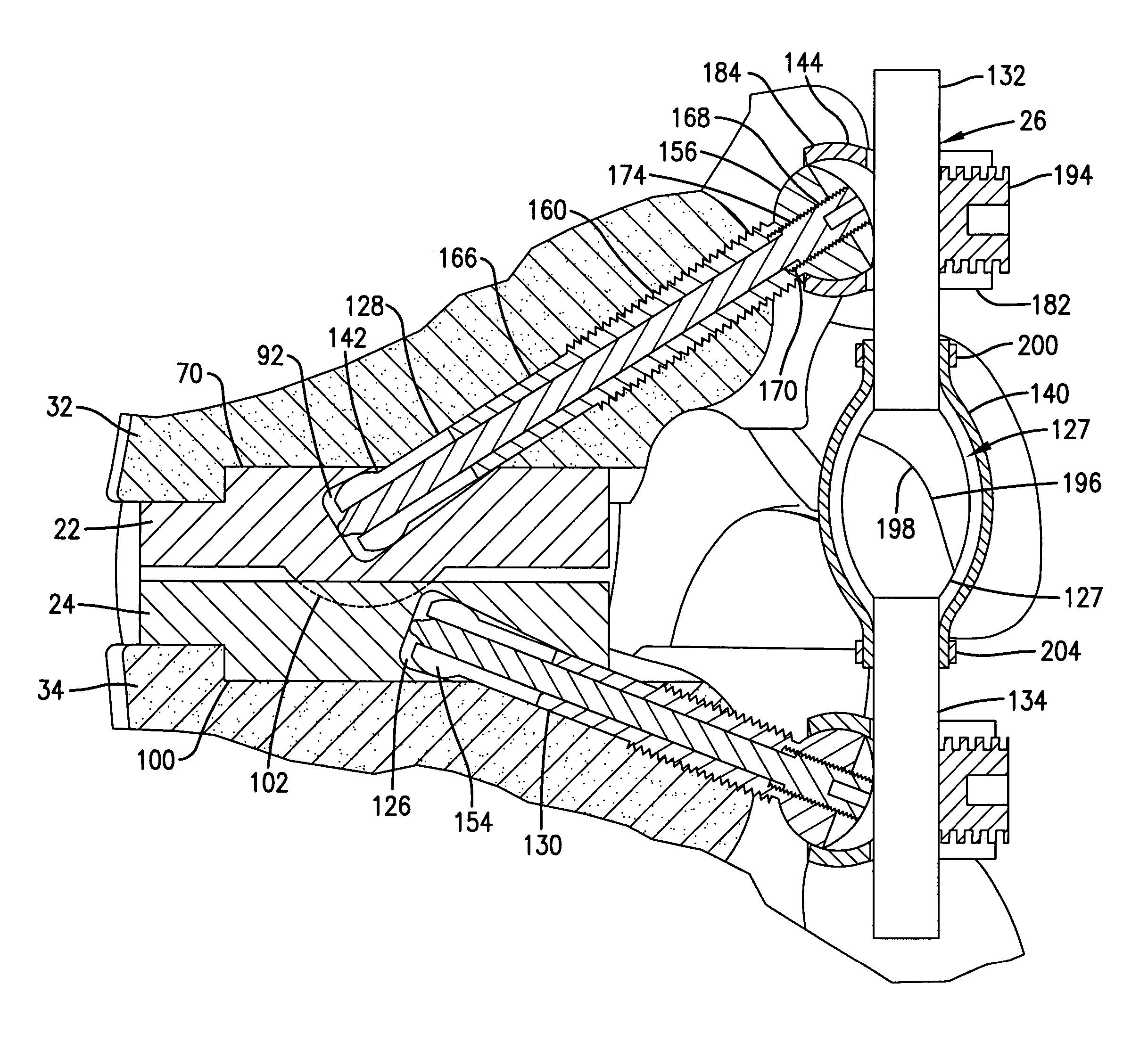
[0012] Broadly speaking, the present invention includes an artificial disc which includes two opposing plate members each having an outrigger which includes a facet to replace the natural facet joint between the inferior articular process of one vertebra and the superior articular process of the adjacent vertebra. Portions of these inferior and superior articular processes are removed during the surgery to permit insertion of the plates from one side of the posterior position of the vertebra. The plate members are complementally configured to permit limited relative motion therebetween. They are also particularly configured with the ribs substantially centered longitudinally and provided with a recess in the ribs to enable mounting of the outriggers. Further, the plate members include a rounded nose configured complementally with the cross-sectional curvature of the natural disc and a relieved edge configured to avoid involvement with the spinal cord. One of the plate members is thus preferably provided with a convex portion which faces a convex portion of the opposing plate member. Ribs extend along the opposite surfaces of the plate members for limiting lateral motion of the plate members once inserted, and permit a unilateral insertion of the plate members between the adjacent vertebrae. The plate members may beneficially be provided with a bio-ingrowth surface to promote bone growth and thus more secure attachment to the vertebra. The outriggers include rods extending through the pedicles of the vertebrae which are attached to the plate members. In addition, the outriggers include respective superior and inferior posts connected to the respective rods, and facet heads on each post which are complementally configured to permit limited relative movement therebetween. The outriggers serve as artificial facets to replace the facet joint between the articular processes removed during surgery, so that support for the patient's spine is not compromised by removal of one of the facets of the vertebra. The other facet of the vertebra can also be replaced if desired using pedicle screws or a second attachment to the plate members of the artificial disc. The artificial facets may be enclosed in a flexible skirt, or alternatively a rigid collar can be provided in surrounding relationship to the artificial facets to help maintain the facets in proximity and further limit the amount of relative movement between the facets.
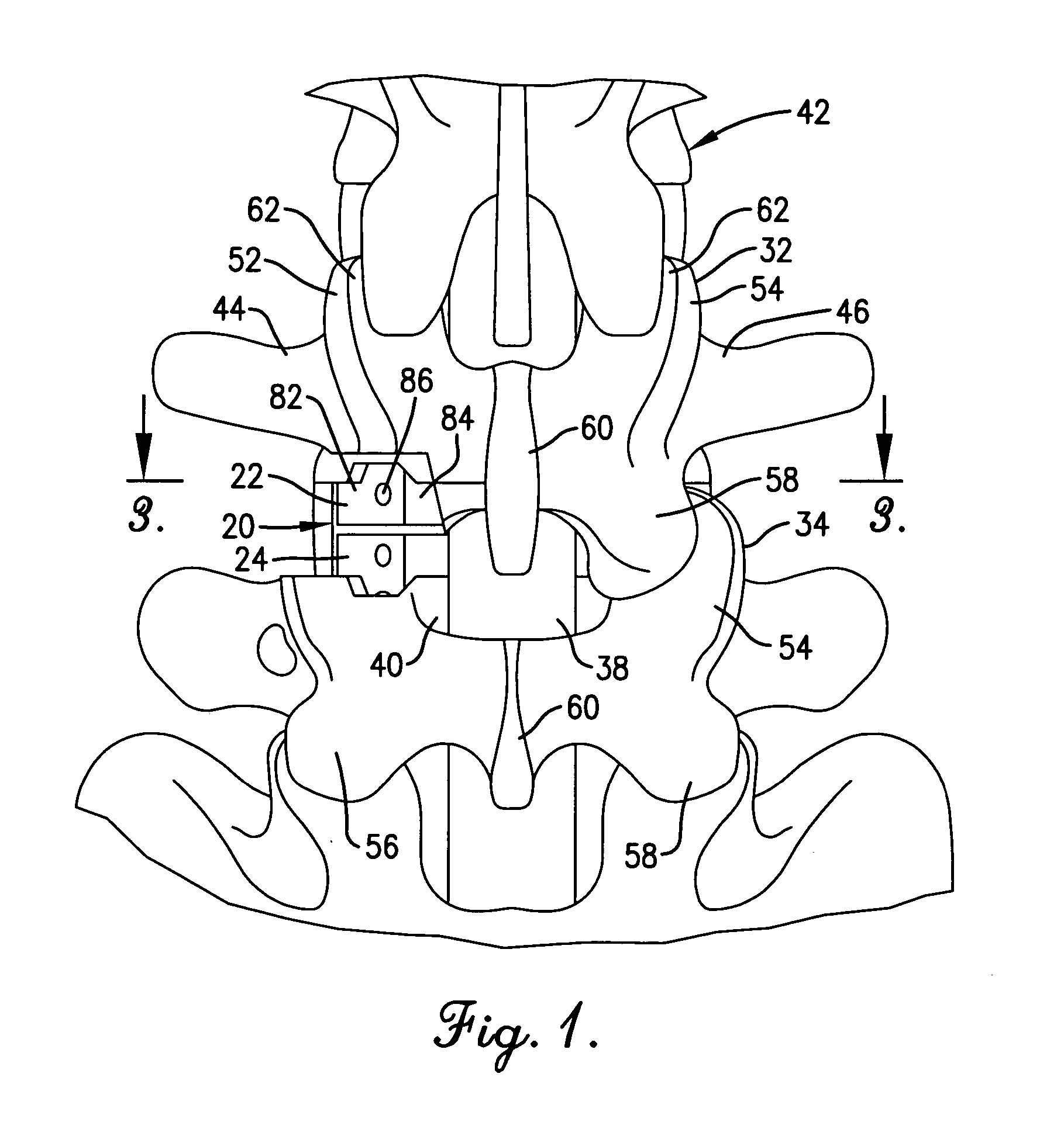
[0013] The present invention also beneficially provides for the cut for receiving and locating the plate members to be made along a single line of insertion—i.e. unilaterally—from generally the posterior of the patient. The provision for a unilateral cut through the natural disc and along each of the adjacent vertebrae provides a good support against lateral movement of the plate members, a favorable interface with the bone, leaves a portion of the natural disc intact for support and cushioning, and makes it easier for the surgeon to make the right cut and avoid errors.
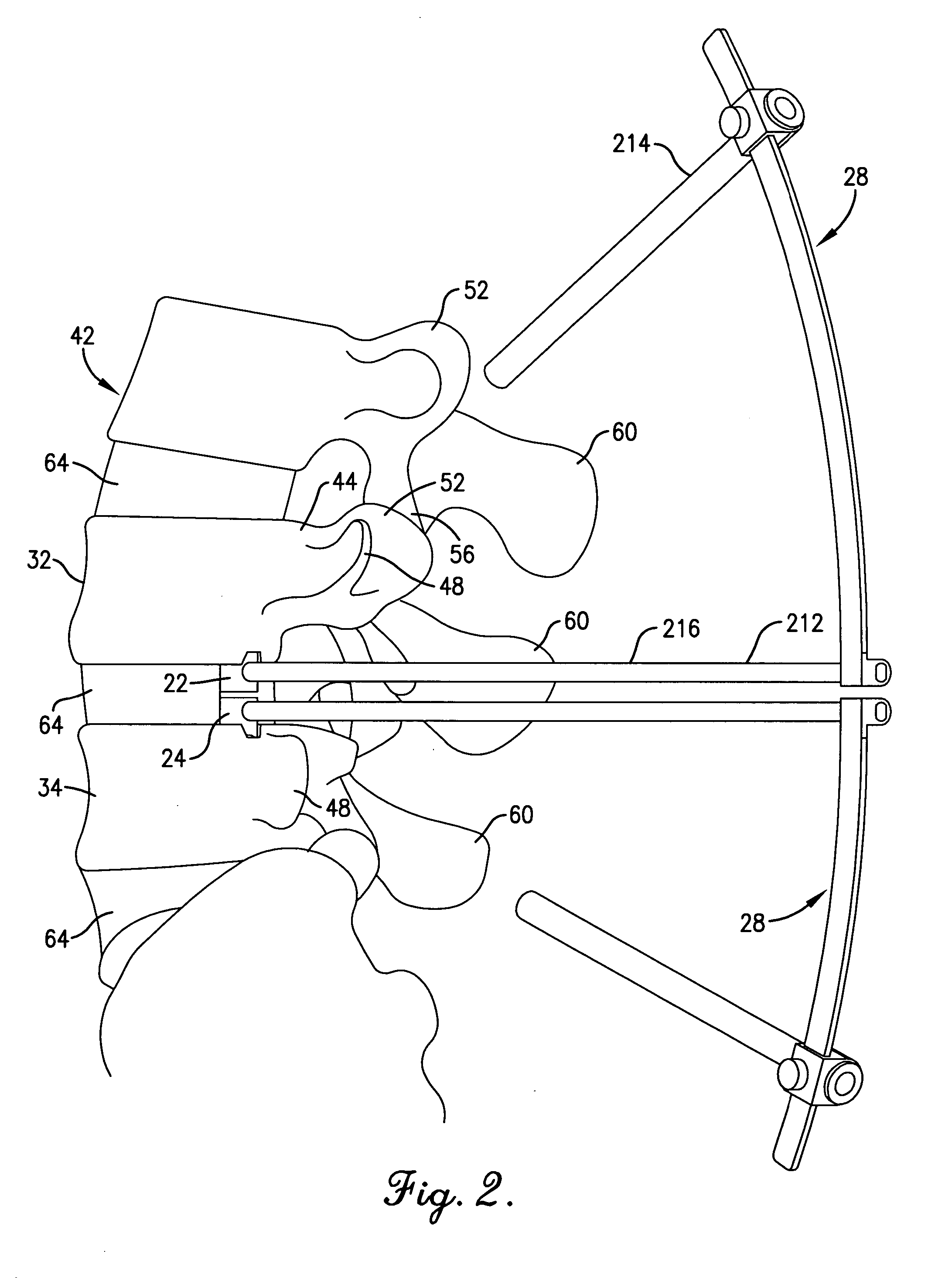
[0014] The invention hereof also includes a novel tool for use during attachment of the outriggers. The tool functions as a guide for use in drilling the channel through the pedicles for receiving the outrigger rods. The tool, which includes a carrier and a drill guide, is advantageously temporarily mounted on one of the plate members and then the other, or two such tools can be employed simultaneously, so that the channel which is drilled is related to the position of the plate members after insertion into the spine, and more particularly the opening into the recess of the plate members. Moreover, the tool is adjustable whereby the surgeon can accommodate variations in individual physiology so that the channel is most advantageously located for the patient. The drill guide is preferably tubular in configuration, having a central axis, and beneficially the central axis intersects at a common point—the opening to the recess of the plate members—when the guide is shifted on the carrier so that the channel created by the drill remains aligned with the opening into which a part of the outrigger is inserted into the plate member.
[0016] It is believed that the present invention will attain the goal of reducing the pain experienced by the patient and restoring most of the original range of motion of the spine. Moreover, it should reduce the risks attendant to anterior insertion of artificial discs whereby the presence of a vascular surgeon will no longer be necessary. These and other benefits will be readily appreciated by those skilled in the art with reference to the drawings and the detailed description set forth below.

Problems solved by technology

One condition which results in significant pain and potential nerve damage, and may require surgery, is a herniated disc.
While such surgery provides a degree of relief to the patient, it necessarily limits flexibility of the spine, which presents a disadvantage for patients with an active lifestyle.
Another disadvantage is the placement of greater loads on the adjacent vertebrae, resulting in what is commonly known as “adjacent segment disease.” Later efforts in the treatment of human disc problems is the use of artificial human discs.
These body parts present significant obstacles to attempts to insert an artificial disc posteriorly.
One problem with such conventional disc replacement systems and methods is that the anterior insertion of the disc does necessitate surgical involvement of the two major blood vessels, the vena cava and the aorta.
Because rupture of either of the vena cava or aorta is life-threatening, such surgery requires the attendance of both a vascular surgeon as well as a spinal surgeon.
Another problem is the difficulty presented in providing artificial discs in two pieces which provide satisfactory support and balance along a single load bearing point as close to the center load line of the spine as possible.

Method used


Image

  • Artificial spinal disc, insertion tool, and method of insertion
  • Artificial spinal disc, insertion tool, and method of insertion
  • Artificial spinal disc, insertion tool, and method of insertion

Examples


Embodiment Construction

[0032] Referring now to the drawings, an artificial spinal disc 20 in accordance with the present invention is shown in FIGS. 9 and 12 and broadly includes first plate member 22 and second plate member 24 with a connecting outrigger 26. The invention further includes a tool 28 used in drilling channels for receiving the outrigger 26, and a spacer tool 30. The artificial spinal disc 20 is designed for use between adjacent first vertebra 32 and second vertebra 34. As used herein, the terms “first vertebra” and “second vertebra” are used merely as a references to distinguish between two adjacent, superior and inferior vertebra, and not in the medical sense as in “sixth cervical vertebra.” As seen in FIGS. 1, 2 and 3 for example, each of the vertebrae 32 and 34 present a vertebral foramen 36 for receiving therein the spinal cord 38, a body 40 which provides a weight bearing capacity for the spinal column 42, left and right pedicles 44 and 46, left and right transverse processes 48 and 5...


PUM


Abstract

An artificial spinal disc is provided for unilateral insertion from the posterior side of the patient and includes a pair of plate members with a bearing associated with one plate member and a depression associated with the other for permitting limited flexibility of patient movement. An outrigger is provided which includes rods extending through the pedicles on one side of each of two adjacent vertebrae and posts connected to the rods which provide an artificial facet joint. A method of insertion of the artificial spinal disc hereof includes cutting channels for receiving longitudinally extending ribs on the plate members and removing the natural facet joint in order to permit insertion of the artificial spinal disc. A tool for insertion of the artificial spinal disc acts as a drill guide for creating a passage through the pedicles.

Description

[0001] This application claims the benefit of U.S. Provisional Application No. 60 / 569,905 filed May 11, 2004.BACKGROUND OF THE INVENTION [0002] 1. Field of the Invention [0003] This invention broadly concerns an artificial disc, insertion tool, and method of insertion for treating conditions of the human spine. More particularly, it is concerned with providing a system and method which advantageously permits insertion of the artificial disc from the posterior region of the patient and provides a unilateral approach with posterior stabilization through fixation through the pedicles of the vertebrae while still allowing the patient to enjoy a range of motion in the area of the artificial disc. [0004] 2. Description of the Prior Art [0005] A number of conditions can result in damage or deterioration of one or more intervertebral discs of the human spine (hereinafter “discs”). A disc may become damaged by external injury or degenerative disc disease due to advanced age in combination wi...

Claims


Application Information

Patent Timeline
Patent Type & Authority Applications(United States)
IPC IPC(8): A61B17/17A61B17/70A61B17/90A61F2/00A61F2/30A61F2/44A61F2/46
CPCA61B17/1757A61F2310/00796A61F2/4405A61F2/4425A61F2002/30337A61F2002/30378A61F2002/30484A61F2002/305A61F2002/30662A61F2002/30769A61F2002/30795A61F2002/30797A61F2002/30884A61F2002/4629A61F2220/0025A61F2220/0033A61F2310/00011A61F2/30742
Inventor BLATT, GEOFFREYBLATT, ERIC
Owner BLATT GEOFFREY
Why Eureka
Try Eureka