Handheld tool for breaking up rock

a tool and rock technology, applied in the direction of dislodge machines, weapons, ammunition fuzes, etc., can solve the problems of large area destruction, use of far more explosive forces, and large explosions, and achieve the effects of easy drilling, portability of the tool, and high skill levels

Inactive Publication Date: 2005-11-24
BASSETT CARROLL
View PDF31 Cites 6 Cited by
  • Summary
  • Abstract
  • Description
  • Claims
  • Application Information

AI Technical Summary

Benefits of technology

[0029] An aspect of the present invention is that the tool and method require very small diameter boreholes, typically about 0.375 inches or smaller, which can be more easily drilled by cheaper and more readily available consumer level equipment. Other methods of cracking hard material require the drilling of relatively large holes, generally an inch in diameter or larger. Alternatively, other methods require strenuous and often dangerous manual labor. The drilling equipment used to accomplish the other methods is expensive and generally requires high skill levels to operate.
[0030] Another aspect of the present invention is that the tool and method generate a relatively low energy output. This low energy output allows operators to use the tool and method in environments sensitive to the use of higher energy methods and devices.
[0031] Yet another aspect of the present invention is the portability of the tool. Since the device is quite small, it can be transported almost anywhere. An example of the usefulness of the small configuration of the tool is the potential use miles underground to open passages in caves for rescue or exploration. The tool easily fits into a hand held carry case with all the essential equipment needed to operate the tool.
[0032] A further aspect gained by the small size and relative simplicity of the system is its projected low cost to own and operate. This coupled with the elimination of large borehole drilling devices will allow many more people to successfully and economically deal with demolition problems in a far easier manner than has previously been available.
[0033] Since the tool's uses are not typically governed by blasting regulations and license requirements in most areas, the tool saves the users money by eliminating the expenses and logistics of hiring separate highly trained and licensed personnel. The tool also eliminates the risks of collateral damage to nearby property, which is always a concern when using high explosives. Many municipalities now have outright bans on the use of high power explosives within their jurisdictions which forces contractors to use track loader mounted hydraulic demolition hammers, pneumatic jack hammers, or expensive and slow acting hydraulic cements to crack materials. All of these methods can cost many times as much as using the present invention and can severely delay projects when unexpected obstacles are encountered.

Problems solved by technology

These devices and methods are typically for large-scale efforts resulting in massive explosions, and the destruction or generation of large areas of rock.
Few devices exist for specialized small scale breaking efforts; however, these devices tend to be larger than the present device and utilize far more explosive forces.
These devices are quite large and produce substantial explosions / gas expansions, and are otherwise unsuitable for the purposes of the present invention.
High water pressure is exerted on the cartridge through a pipe resulting in a sudden explosive release of pressure increasing substance from the cartridge.
The requirement of a separate apparatus for sealing pressurized fluids into bore holes is inconvenient especially in any emergency rescue operations where the least amount of equipment, especially bulky equipment, in most desirable.
Specifically, these devices lack the simplicity and portability desired for truly small-scale rock breaking, and especially, for rock breaking that must not generate an explosion of any significant force.

Method used


Image

  • Handheld tool for breaking up rock
  • Handheld tool for breaking up rock
  • Handheld tool for breaking up rock

Examples


first embodiment

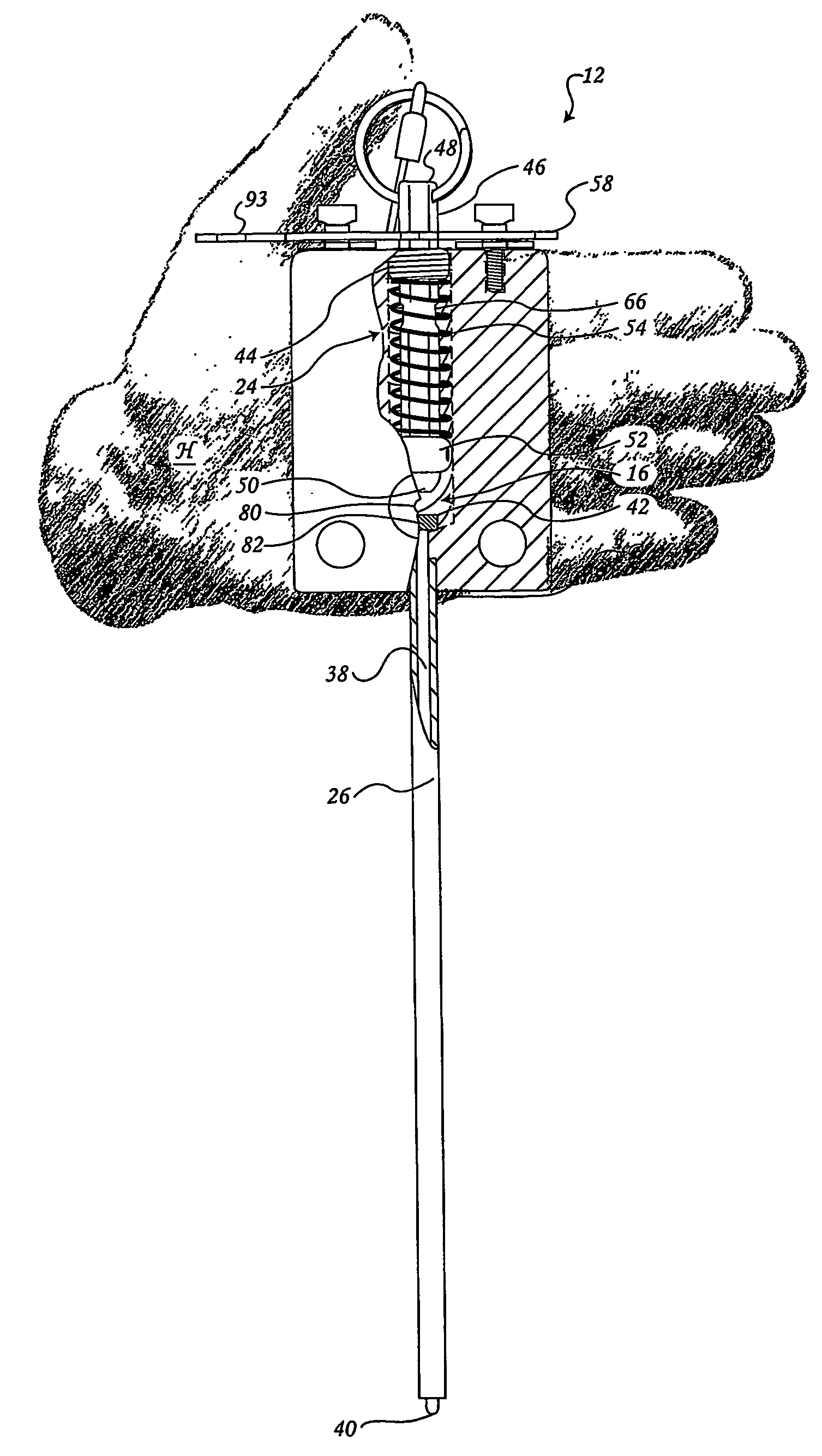
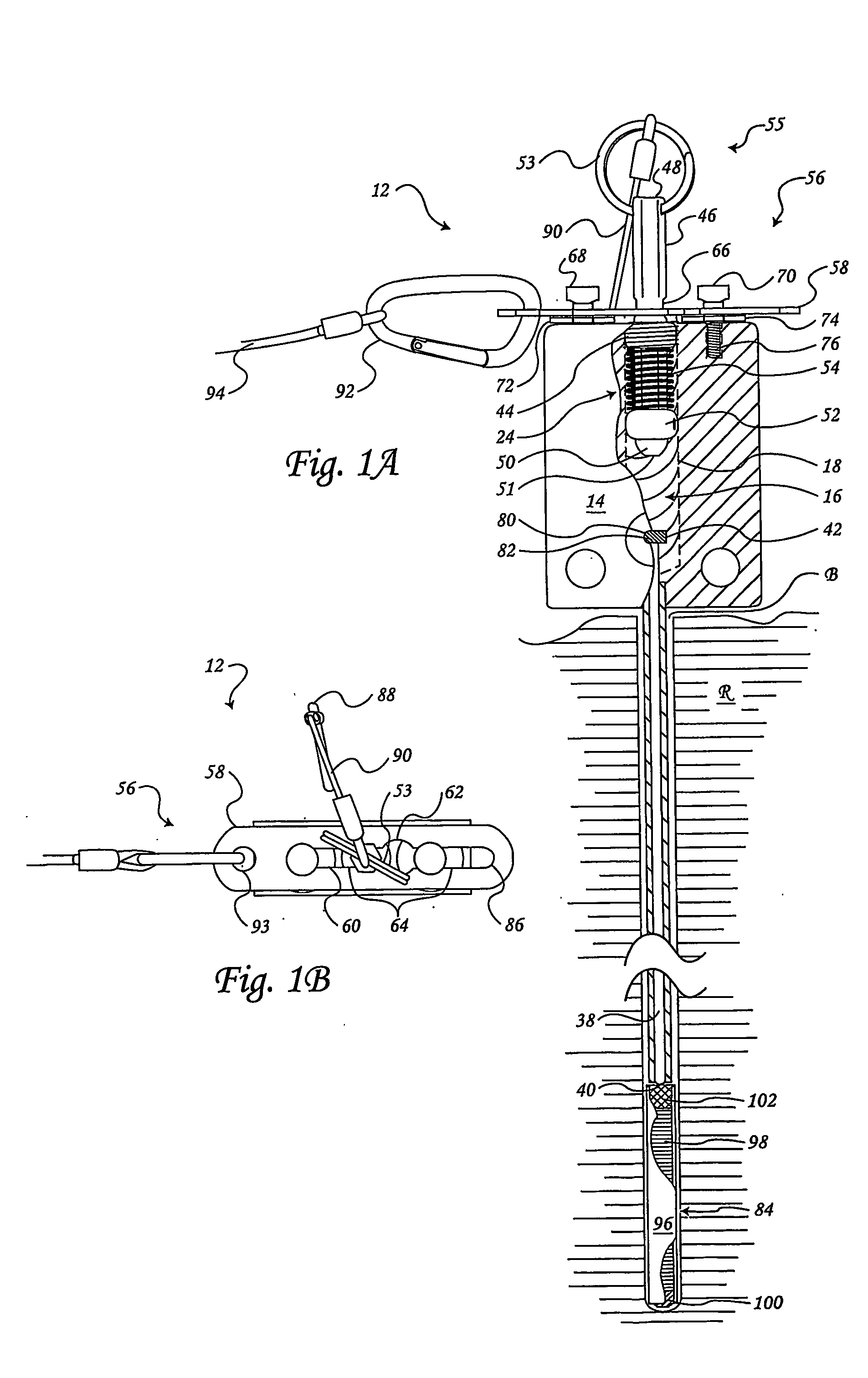
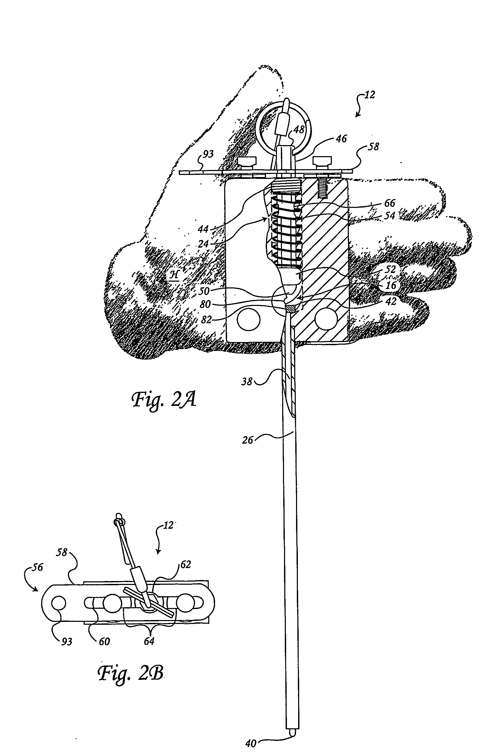
[0060] A first embodiment of the cartridge (84), used with the present invention, is shown in a cutaway borehole (B) of FIG. 1. the cartridge (84) has a tubular shaped casing (96) having a bottom which may be a plug (100), at one end and a primer (102) at the opposing end. The propellant or load (98) is disposed within the casing (96) between the bottom (100) and the primer (102). A second embodiment of the cartridge (84′) is shown in FIG. 5. The second embodiment of the load cartridge (84′) has a test tube shaped casing (96′) with a primer (102) at the open end. The propellant (98) is disposed within the casing (96′), as shown in FIG. 5. The present invention is not limited to the use of the cartridges (84 and 84′) shown but encompasses all possible embodiments of a scale-to-tool fit load cartridge, which can be detonated by a force on the primer through an actuator pin (38) and hammer (46) according to the present invention. The primer (102) may be comprised of a conventional 209 ...


PUM


Abstract

A tool (12) has a body (14) with a barrel (18) having opposing threaded and fitted openings (30 and 28). An actuator pin tube (26), for slidably engaging an actuator pin (38) having a tip (40) opposing a retention head (42), extending from the fitted opening (30). A spring assembly (24), disposed in the barrel (18), has a hammer guide (44) engaged in the threaded opening (28) with a hammer (46) slidably engaged therein, a handle mechanism (55) disposed at one end and a spring retainer (52) disposed adjacent the other end of the hammer (46) before a hammerhead (51), and a spring (54) engaged between the hammer guide (44) and the spring retainer (52). A release mechanism (56) engages the hammer (46). A kit (108) containing the tool (12) and a method of operating the tool (12) involving drilling and cleaning a borehole, inserting a cartridge and tool therein, and detonating the load remotely using a pull cord.

Description

RELATED APPLICATIONS [0001] This application claims the benefit of U.S. Provisional Application Ser. No. 60 / 400,502 filed on 5 Aug. 2002, the contents of which are incorporated herein by reference in its entirety.FIELD OF THE INVENTION [0002] The present invention relates to a tool and a method for breaking up rock, and in particular, to a handheld remote detonation tool, a kit containing the tool, and a method for breaking rock, masonry and the like using the tool and kit. BACKGROUND OF THE INVENTION [0003] Numerous devices have been utilized in the art of breaking up rock. Most such devices are quite large, and are used in mining, quarries and excavation endeavors. These devices and methods are typically for large-scale efforts resulting in massive explosions, and the destruction or generation of large areas of rock. Few devices exist for specialized small scale breaking efforts; however, these devices tend to be larger than the present device and utilize far more explosive forces...

Claims


Application Information

Patent Timeline
Patent Type & Authority Applications(United States)
IPC IPC(8): E21B7/00F41F5/00F42C7/12F42D1/04F42D3/04
CPCE21B7/007F42C7/12F42D1/04F42D3/04
Inventor BASSETT, CARROLL
Owner BASSETT CARROLL
Why Eureka
Try Eureka