Dye-sensitized solar cell and dye-sensitized solar cell module

a solar cell and dye-sensitized technology, applied in the direction of pv power plants, electrolytic capacitors, electrochemical generators, etc., can solve the problems of high manufacturing costs, unresolved problems, and high manufacturing costs of silicon substrates, and achieve solar cells, high efficiency, and easy manufacturing.

Active Publication Date: 2005-11-24
SHARP KK
View PDF24 Cites 24 Cited by
  • Summary
  • Abstract
  • Description
  • Claims
  • Application Information

AI Technical Summary

Benefits of technology

[0015] Through earnest studies in view of the above-mentioned problems, the inventors of the present invention have completed the present invention by finding out that the use of a shape appropriate for achieving high efficiency of a dye-sensitized solar cell allows the solar cell to be manufactured more easily than the conventional art, so as to further obtain a dye-sensitized solar cell having an increased photocurrent density and a high conversion efficiency, and a dye-sensitized solar cell module employing this.

Problems solved by technology

However, the former has a problem in high manufacturing costs of a silicon substrate, and the latter has a problem in that it is necessary to employ various kinds of semiconductor gases and complicated devices.
Therefore, it is still high in manufacturing costs.
Thus, an effort to reduce costs per output of electric power generation by achieving a high efficiency of photoelectric conversion has been made in both of the solar cells, but the above-mentioned problems have not been solved yet.
Accordingly, even though a solar cell with a small area can be experimentally manufactured, the application to a solar cell with a large area such as 1 meter square becomes difficult.
As a result, there arises a problem in that a curve factor (fill factor; FF) in current-voltage characteristics during photoelectric conversion is decreased and photoelectric conversion efficiency is decreased.
One solar cell (unit cell), however, is simply made larger in area, whereby there arises a problem in that an increase in internal series resistance makes difficult to achieve a large area in the same way as the above.
Thus, a large area of a gap brings no contribution of light onto the gap to electric power generation, so that module conversion efficiency becomes poor even though the conversion efficiency of a unit cell composing the module is high.
The manufacturing costs per unit output also tend to become high.
Generally, the amorphous silicon solar cell is subjected to scribing and integrated patterning by laser or the like, which these processes are applied to a dye-sensitized solar cell with difficulty.
A minute pattern can not be formed by laser or the like on such a porous body for the reason that a portion on which a minute pattern is formed is poor in strength.
In addition, use of the laser raises manufacturing costs.
It is, however, impossible to form a shape shown in FIG. 5 only by the screen printing process, and after the porous photovoltaic layer is formed, patterning is performed by laser, air jet or the like, so that the same problem arises for the same reason as the above.
It is difficult that a second conductive layer is uniformly formed on the porous photovoltaic layer manufactured in the above-mentioned manufacturing method.
For example, in the case where a second conductive layer of one unit cell is contacted with a first conductive layer of an adjacent unit cell, a decrease in the efficiency of the dye-sensitized solar cell results from an increase in resistance and, additionally, the occurrence of a short-circuit due to the extreme thinning of a second conductive layer on the side of a porous photovoltaic layer.
Meanwhile, a method is also conceived such that a resin or the like is printed with a predetermined pattern, which is utilized for forming a porous photovoltaic layer and a second conductive layer; however, this method offers complicated operation processes, so that manufacturing tact is deteriorated and costs are raised.

Method used


Image

  • Dye-sensitized solar cell and dye-sensitized solar cell module
  • Dye-sensitized solar cell and dye-sensitized solar cell module
  • Dye-sensitized solar cell and dye-sensitized solar cell module

Examples


example 1

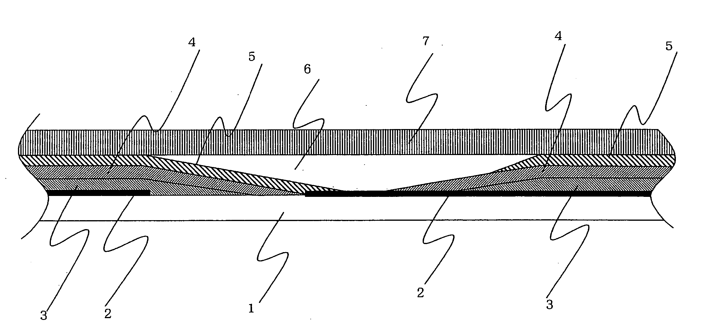
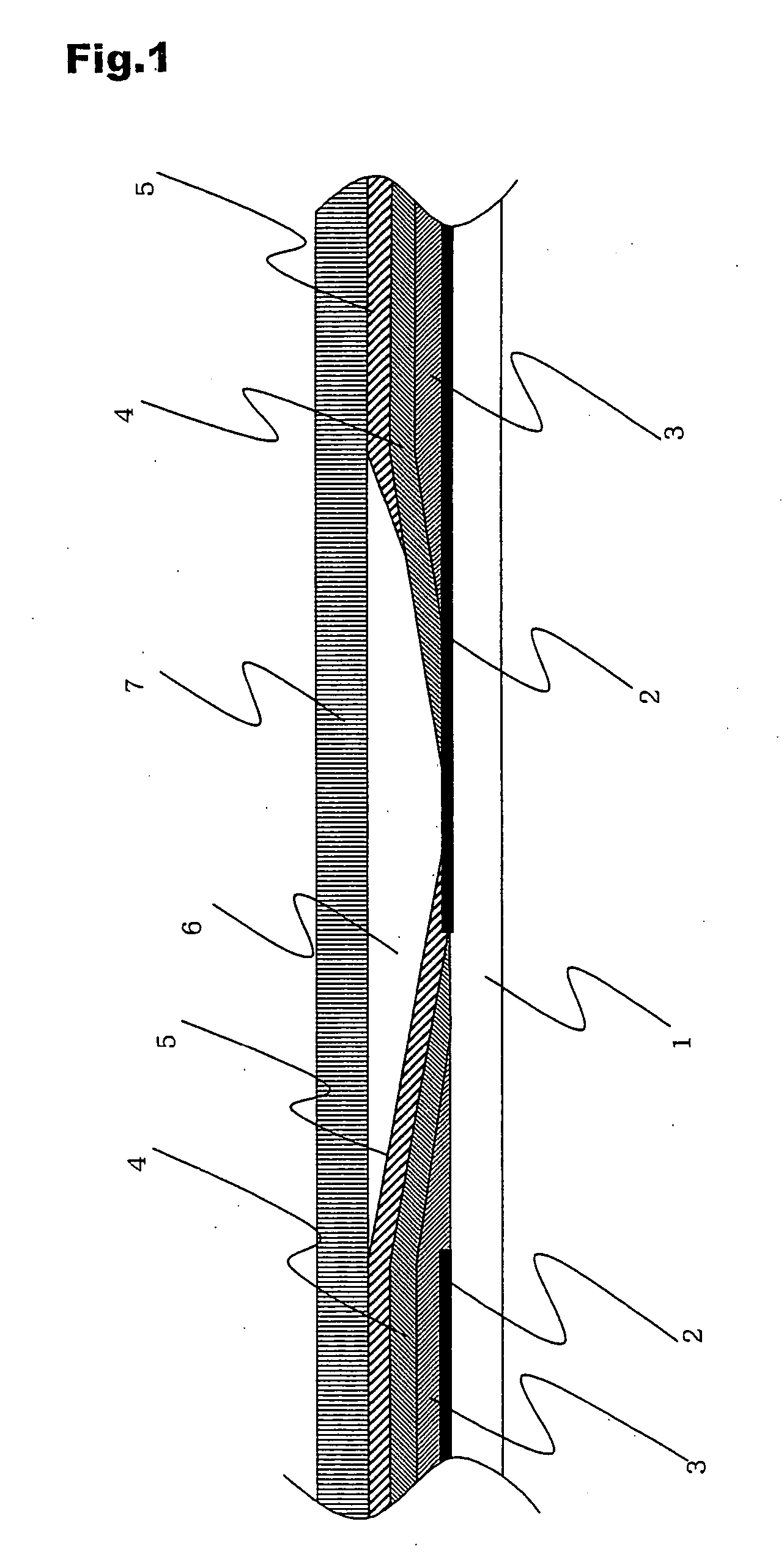
[0100] An integrated dye-sensitized solar cell module was manufactured, such that 10 unit cells are connected in series. Manufacturing processes thereof are described below. A series connection portion is a structure shown in FIG. 1.

[0101] As a substrate, used was a glass substrate (first support 1) of 10 mm×10 mm, manufactured by Nippon Sheet Glass Co., Ltd., with fluorine-doped SnO2 (first conductive layer 2). SnO2 was irradiated with laser light (YAG laser, fundamental wavelength: 1.06 μm) so as to be in the shape of a strip having a width of 1.035 cm and a gap between adjacent unit cells of 350 μm, and then patterning was performed by vaporizing SnO2.

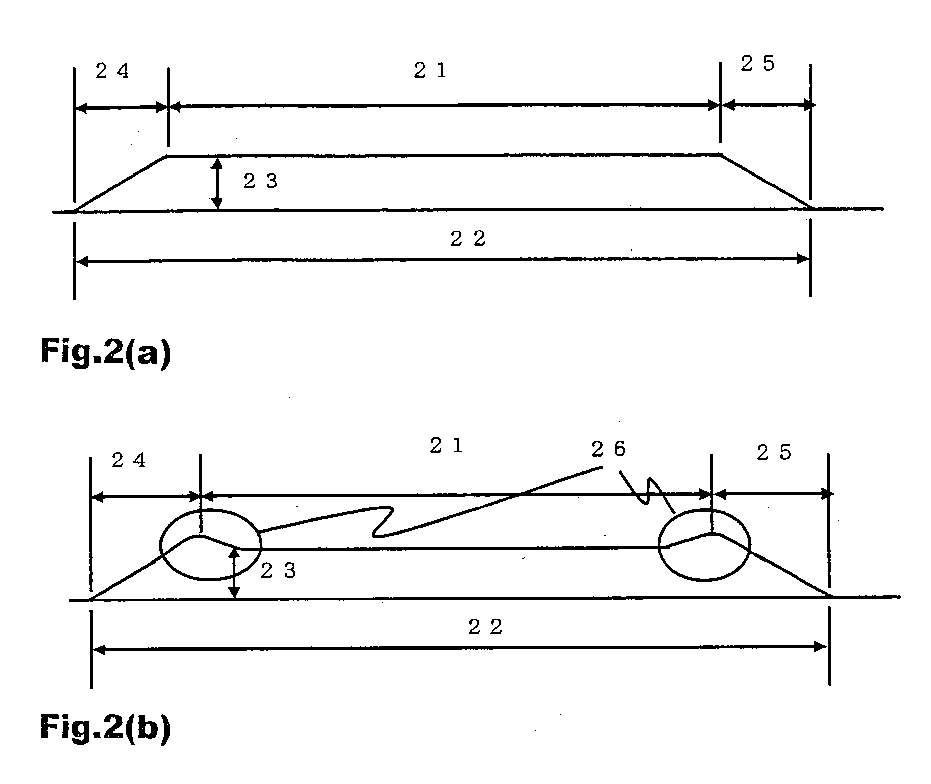
[0102] Next, a porous photovoltaic layer 3 after firing was manufactured by a screen printing machine so that a shape was 1 cm×9 cm, a film thickness was 15 μm, the shortest distance X between the intersection of the perpendicularly drawn from the surface edge of the confronted side of the porous photovoltaic layer to the contact ...

example 2

[0108] A dye-sensitized solar cell module having the porous photovoltaic layer 3 in which the dimensionless number K was 0.15 and the shortest distance X between the intersection of the perpendicularly drawn from the surface edge of the confronted side of the porous photovoltaic layer to the contact side of the porous photovoltaic layer and the surface edge of the contact side was 100 μm was manufactured in conformance with Example 1. The obtained dye-sensitized solar cell module had the short-circuit current density of 11.08 mA / cm2, the open-circuit voltage value was 6.50 V, the FF of 0.53 and the module conversion efficiency of 3.82%.

example 3

[0109] A dye-sensitized solar cell module having the porous photovoltaic layer 3 in which the dimensionless number K was 0.03, the shortest distance X between the intersection of the perpendicularly drawn from the surface edge of the confronted side of the porous photovoltaic layer to the contact side of the porous photovoltaic layer and the surface edge of the contact side was 330 μm, and the film thickness was 10 μm was manufactured in conformance with Example 1. The performance of the obtained dye-sensitized solar cell module offered the results shown in Table 1.


PUM

PropertyMeasurementUnit
thicknessaaaaaaaaaa
lengthaaaaaaaaaa
lengthaaaaaaaaaa

Abstract

A dye-sensitized solar cell comprising a first support, a first conductive layer, a porous photovoltaic layer containing a dye, a carrier transport layer and a second conductive layer stacked in this order, wherein the length of contact side of the porous photovoltaic layer closed to the first conductive layer is different from that of its confronted side of the porous photovoltaic layer.

Description

CROSS-REFERENCES TO RELATED APPLICATIONS [0001] This application is related to International Application No.PCT / JP2003 / 012805 filed on Oct. 6, 2003 on which the priority of Japanese patent application No. 2002-300801 filed on Oct. 15, 2002 is claimed, disclosures of said applications being incorporated by reference in their entirety. TECHNICAL FIELD [0002] The present invention relates to a dye-sensitized solar cell and a dye-sensitized solar cell module. BACKGROUND ART [0003] A solar cell capable of converting sunlight into electric power has been noted as an energy source substituting for fossil fuel. Currently, examples of a solar cell, which began to be partially put to practical use, include a solar cell employing a crystalline silicon substrate, and a thin-film silicon solar cell. However, the former has a problem in high manufacturing costs of a silicon substrate, and the latter has a problem in that it is necessary to employ various kinds of semiconductor gases and complicat...

Claims


Application Information

Patent Timeline
Patent Type & Authority Applications(United States)
IPC IPC(8): H01L31/00H01L31/04H01M14/00
CPCH01G9/2031Y02E10/542H01G9/2081H01G9/2059
Inventor YAMANAKA, RYOHSUKEHAN, LIYUAN
Owner SHARP KK
Why Eureka
Try Eureka