Liquid crystal display driver device and liquid crystal display system

a driver device and liquid crystal display technology, applied in the direction of instruments, static indicating devices, etc., can solve the problems of large increase in the cost of the source driver, increased time from image data input until analog voltage output, and wasted space, etc., to achieve the effect of suppressing the increase in the chip siz

Inactive Publication Date: 2005-11-24
RENESAS TECH CORP
View PDF10 Cites 48 Cited by
  • Summary
  • Abstract
  • Description
  • Claims
  • Application Information

AI Technical Summary

Benefits of technology

[0008] It may be considered to regulate the number of image signal output terminals of a source driver and construct a liquid crystal display system by using a plurality of source drivers. This method is effective from the viewpoint of decreasing the chip size of the source driver. In this case, however, it is necessary to pay attention to timings of switching the source driver to which image data is to be sent. When the timings are inaccurate, image data may not be accurately sent to the source driver and transmission time for transmitting image data to the source driver may increase.
[0025] A display driver device (liquid crystal driver, semiconductor integrated circuit for driving liquid crystal) capable of performing display with high-level gradation while suppressing increase in the chip size can be realized.

Problems solved by technology

Even if the D / A converting circuits are disposed under the wires for supplying the gradation voltages (also called power supply lines), wasted space occurs.
The inventors herein have found that the size of a semiconductor chip on which a liquid crystal driver, that is, a source driver is formed increases and it causes large increase in the cost of the source driver.
In the method, however, time since image data is input until analog voltage is output becomes longer.
The inventors herein, however, have also found that the method is not effective because the chip size of such a source driver is extremely large.
When the timings are inaccurate, image data may not be accurately sent to the source driver and transmission time for transmitting image data to the source driver may increase.

Method used


Image

  • Liquid crystal display driver device and liquid crystal display system
  • Liquid crystal display driver device and liquid crystal display system
  • Liquid crystal display driver device and liquid crystal display system

Examples


Embodiment Construction

[0042] Preferred embodiments of the invention will be described hereinbelow with reference to the drawings.

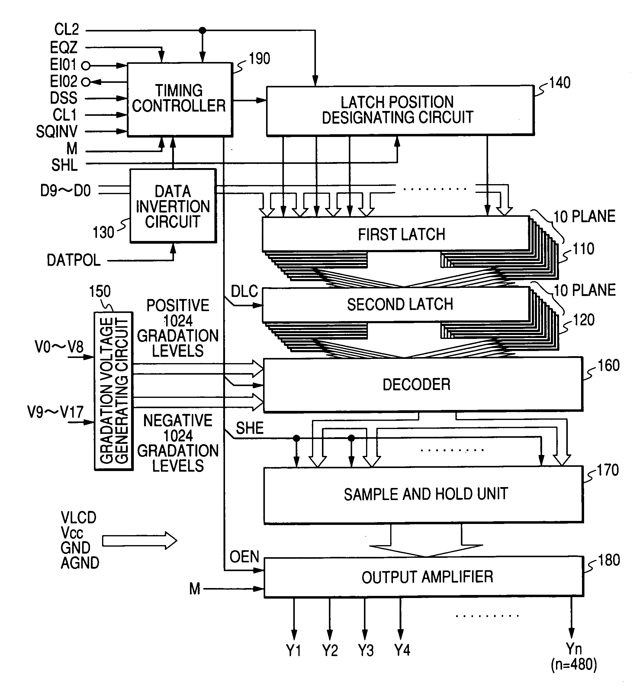
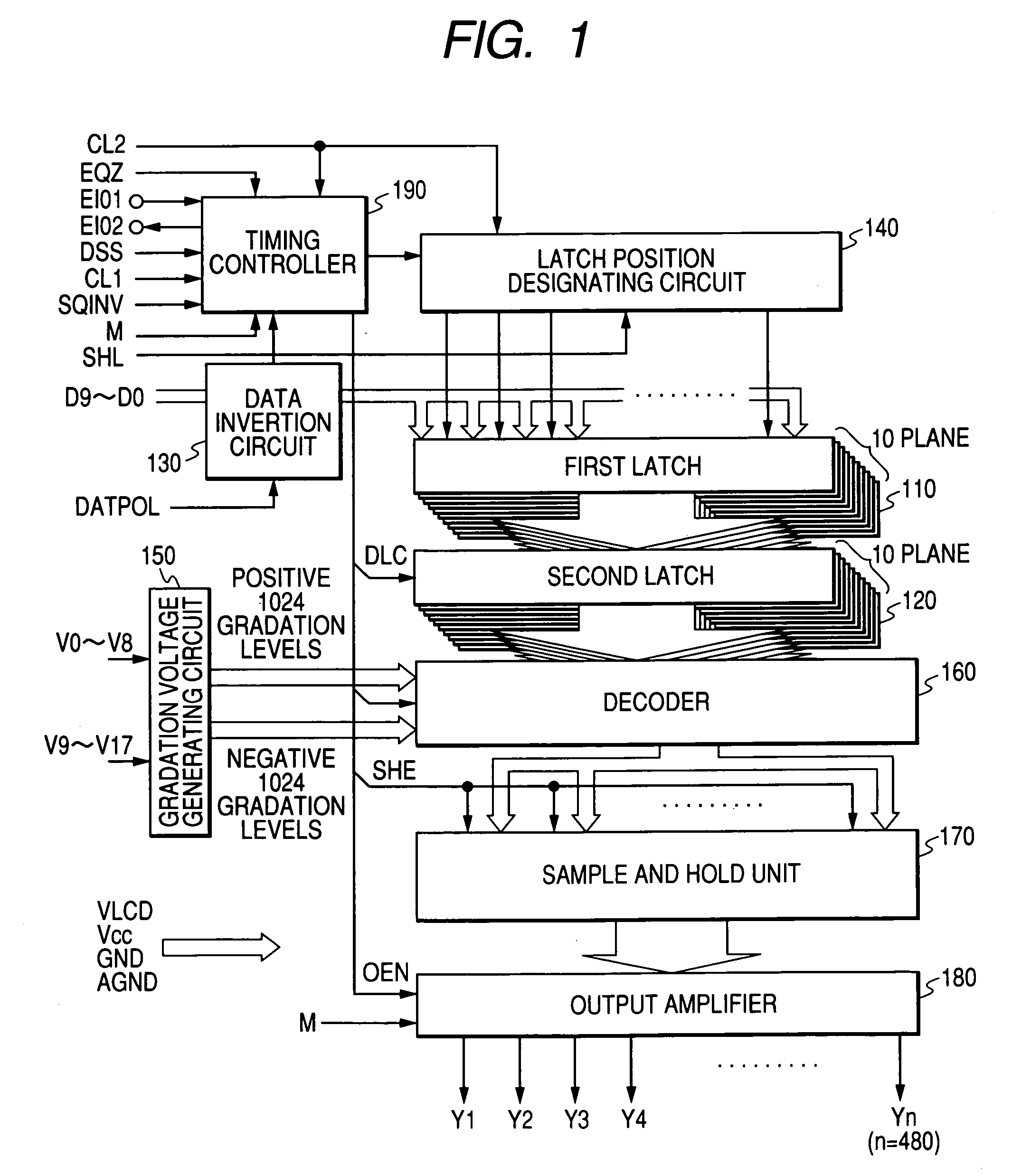
[0043]FIG. 1 shows a schematic configuration of a liquid crystal driver circuit to which the invention is applied. Although not limited, circuit blocks shown in FIG. 1 are constructed as semiconductor integrated circuits on a single semiconductor chip made of single crystal silicon or the like. The liquid crystal driver circuit of the embodiment is a circuit for outputting image signals Y1 to Yn to be applied to signal lines of a color liquid crystal panel of a dot matrix type in which a plurality of scan lines and a plurality of signal lines are arranged in a lattice shape and pixels are provided at intersecting points.

[0044] An embodiment of the invention will be described on assumption that, although not limited, pixel data of one pixel consists of 30 bits; 10 bits of color data of red (R), 10 bits of color data of green (G), and 10 bits of color data of blue (B).

[0045] A...


PUM

PropertyMeasurementUnit
voltageaaaaaaaaaa
coloraaaaaaaaaa
drive voltageaaaaaaaaaa

Abstract

The present invention is directed to reduce the size of a liquid crystal driver (semiconductor integrated circuit for driving liquid crystal) having therein a D / A converting circuit, converting digital image data to analog gradation voltage, and outputting a voltage to be applied to a signal line (source line) of a color liquid crystal panel. Output amplifiers of the final stage for outputting an image signal converted to gradation voltage are divided into a plurality of groups. D / A converting circuits for converting image data to gradation voltage are provided as circuits common to the groups. While switching the group, the D / A converting circuit is operated in a time sharing manner. The output amplifiers in the final stage related to image signals of the same color are selected and grouped. A selector function is provided between the D / A converting circuit and the output amplifier, and an image signal converted to gradation voltage by the D / A converting circuit is supplied to a desired hold circuit.

Description

CROSS-REFERENCE TO RELATED APPLICATION [0001] The present application claims priority from Japanese patent application No 2004-150016 filed on May 20, 2004, the content of which is hereby incorporated by reference into this application. BACKGROUND OF THE INVENTION [0002] The present invention relates to a display driver device for driving a color display panel, a liquid crystal display driver device for driving a color liquid crystal panel and, further, a technique effective when applied to a liquid crystal display driver device formed on a semiconductor integrated circuit. The invention relates to, for example, a technique effective for use in a liquid crystal display driver device for driving a color liquid crystal display panel of a color television system. [0003] A liquid crystal display system as one of display systems includes a liquid crystal display panel (hereinbelow, also called a liquid crystal panel) as a display panel, a liquid crystal display controller (liquid crystal...

Claims


Application Information

Patent Timeline
Patent Type & Authority Applications(United States)
IPC IPC(8): G02F1/133G09G3/20G09G3/36
CPCG09G3/3688G09G2310/0297G09G2310/027G09G3/20G09G3/36
Inventor YAMAGUCHI, SATOSHIENDO, MASUHIROKUBO, TAKEHIKO
Owner RENESAS TECH CORP
Why Eureka
Try Eureka