Method and apparatus for measuring and controlling selective catalytic reduction (SCR) emission control systems

a selective catalytic reduction and emission control technology, applied in the direction of nitric oxide, machine/engine, chemical/physical processes, etc., can solve the problems of improper control, degradation of scr catalyst, reactivity of scr catalyst over time, etc., to facilitate the reaction of pollution

Inactive Publication Date: 2005-11-24
GENERAL ELECTRIC CO
View PDF22 Cites 34 Cited by
  • Summary
  • Abstract
  • Description
  • Claims
  • Application Information

AI Technical Summary

Benefits of technology

[0008] Some configurations of the present invention therefore provide a method for monitoring and / or controlling performance of a selective catalytic reduction (SCR) emission control system. The method includes injecting a quantity of a pollution neutralizing gas into a combustion gas stream containing a pollutant gas, passing the stream over a catalyst bed to facilitate a reaction of the pollution neutralizing gas with the pollutant gas to produce an effluent, and measuring a ratio of the pollution neutralizing gas to the pollutant gas in the effluent.
[0009] Various configurations of the present invention also provide an apparatus for monitoring and controlling performance of a selective catalytic reduction (SCR) emission control system. The apparatus is configured to measure a ratio of pollution neutralizing gas to pollutant gas in a flue gas stream effluent downstream of a catalyst, and adjust an injected quantity pollution neutralizing gas in a flow of gas including the pollutant gas upstream of or at the catalyst in accordance with the measured ratio.
[0010] Some configurations of the present invention provide a gas turbine combustion plant having a selective catalytic reduction (SCR) emission control system that includes a catalyst bed. The plant also includes a supply of a pollution neutralizing gas for reacting with a pollutant gas in the SCR system and a measuring system configured to measure a ratio of the pollution neutralizing gas to pollutant gas in an effluent of the SCR system.
[0011] Still other configurations of the present invention provide a fossil fuel-fired boiler having a selective catalytic reduction (SCR) emission control system. The SCR include a catalyst bed, and the plant also has a supply of a pollution neutralizing gas for reacting with a pollutant gas in the SCR system. A measuring system that is configured to measure a ratio of the pollution neutralizing gas to pollutant gas in an effluent of the SCR system is also provided.

Problems solved by technology

Two issues faced by owners and operators of facilities equipped with Selective Catalytic Reduction (SCR) systems include proper control of the ammonia distribution across the face of the catalyst (or to different SCR modules) and deterioration of the SCR catalyst.
If there is excessive ammonia flow, then the ammonia (considered a hazardous air pollutant in several states) will pass through the system unreacted.
One of the first challenges faced during start up of a new SCR system is to achieve proper balancing of the AIG.
This can be caused by many system variables such as fouling of the injection nozzles, plugging of the ammonia transport lines, or shifts in the spatial distribution of the inlet NOx at the inlet to the SCR (or between different SCR modules).
Also, the reactivity of an SCR catalyst degrades over time.
Typically, catalyst performance will remain acceptably high for periods of 3 to 10 years but occasionally the reactivity can decline precipitously.
A sharp drop in reactivity can occur due to many factors including catalyst poisoning or delamination of a wash coat type catalyst.
This method has proven satisfactory for SCR systems that operate at sub-stoichiometric ammonia levels, but is less satisfactory for systems that operate at near 1:1 inlet NOx to ammonia ratio or for facilities with stringent ammonia slip regulatory limits.
The known method also does not provide continuous monitoring to detect deterioration in AIG balancing.
Also, at least one known method physically extracts catalyst samples on a regular basis and subjects the catalyst to reactivity testing at a remote laboratory, but does not monitor catalyst performance during yearlong periods between major plant outages.
Some indication of catalyst performance is provided through continuous measurement of overall NOx destruction efficiency but those data cannot distinguish the impacts of AIG tuning from catalyst reactivity.

Method used


Image

  • Method and apparatus for measuring and controlling selective catalytic reduction (SCR) emission control systems
  • Method and apparatus for measuring and controlling selective catalytic reduction (SCR) emission control systems
  • Method and apparatus for measuring and controlling selective catalytic reduction (SCR) emission control systems

Examples


Embodiment Construction

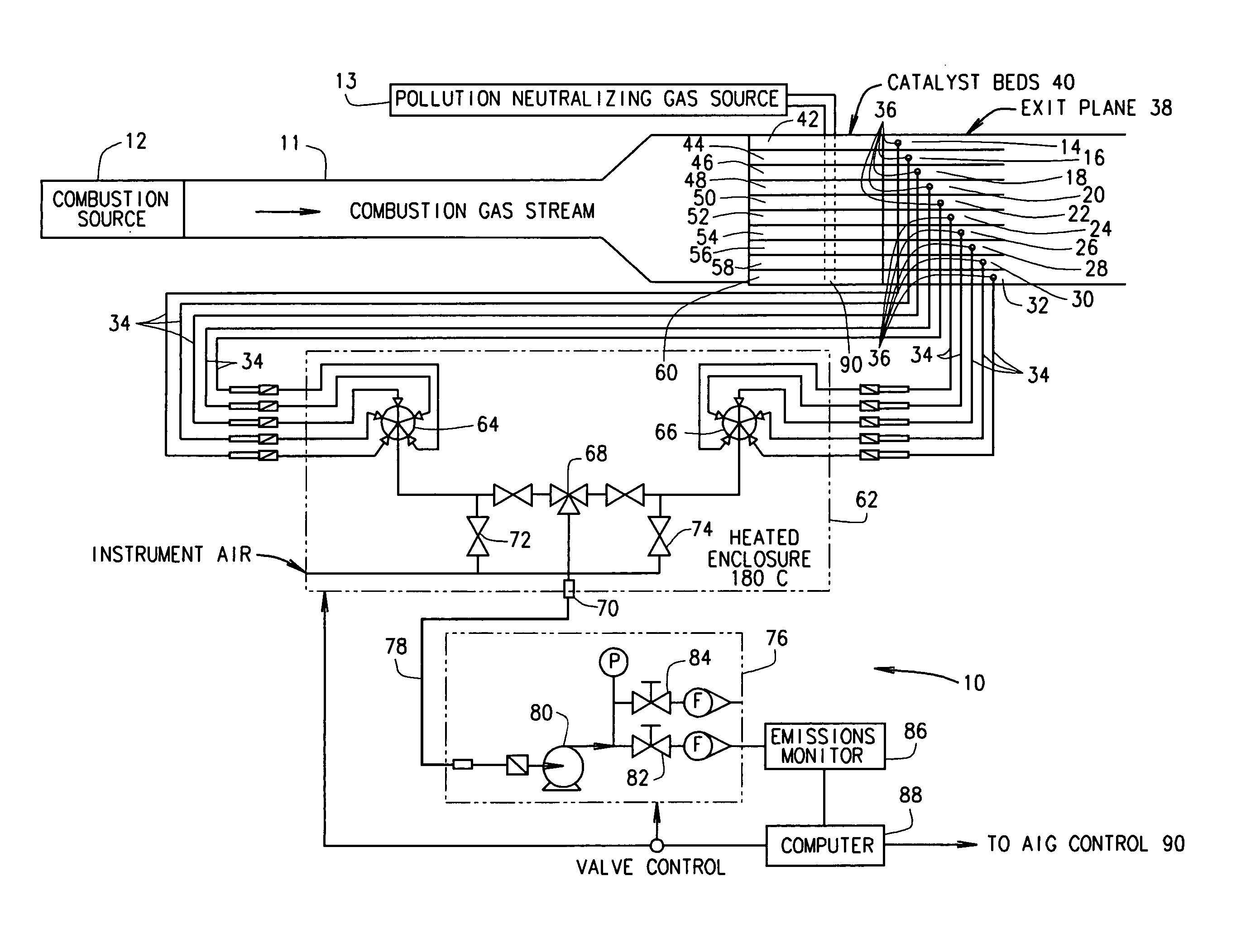
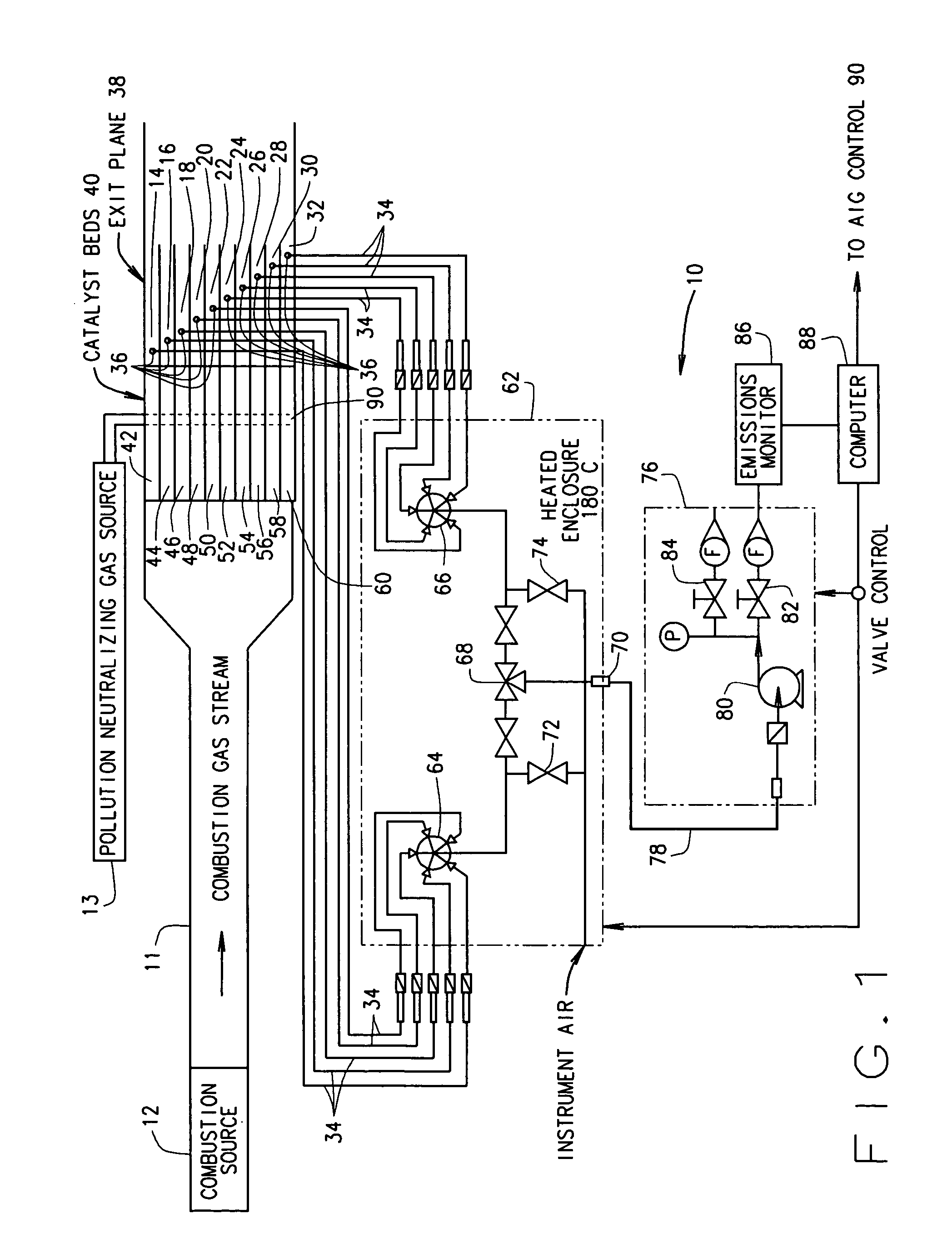
[0018] In some configurations of the present invention and referring to FIG. 1, a selective catalytic reduction (SCR) measuring and control system 10 is provided for reducing pollution from a combustion source 12. A non-exhaustive list of such combustion sources includes gas turbine combustion sources, fossil fuel-fired combustion sources, and industrial processes (for example, quartz manufacturing). Combustion source 12 produces a combustion gas stream containing a pollutant gas, for example, NOx. A quantity of a pollution neutralizing gas 13 (e.g., NH3) is injected into combustion gas stream 11 at or upstream from a catalyst 40 using an injection grid 90 such as an ammonia injection grid (AIG) 90.

[0019] (It is recognized that ammonia is considered a hazardous air pollutant in many states. However, referring to ammonia as a “pollution neutralizing gas” should not result in any confusion to one of ordinary skill in the art. Ammonia is referred to herein as a “pollution neutralizing...


PUM

PropertyMeasurementUnit
constant temperatureaaaaaaaaaa
concentrationaaaaaaaaaa
time-averaged ratiosaaaaaaaaaa

Abstract

A method for monitoring and/or controlling performance of a selective catalytic reduction (SCR) emission control system includes injecting a quantity of a pollution neutralizing gas into a combustion gas stream containing a pollutant gas. The method also includes passing the stream over a catalyst bed to facilitate a reaction of the pollution neutralizing gas with the pollutant gas to produce an effluent and measuring a ratio of the pollution neutralizing gas to the pollutant gas in the effluent.

Description

BACKGROUND OF THE INVENTION [0001] This invention relates generally to pollution reduction systems, and more particularly to methods and apparatus for monitoring and controlling selective catalytic reduction emission control systems. [0002] Two issues faced by owners and operators of facilities equipped with Selective Catalytic Reduction (SCR) systems include proper control of the ammonia distribution across the face of the catalyst (or to different SCR modules) and deterioration of the SCR catalyst. [0003] An SCR is capable of achieving high levels of NOx destruction by injecting controlled quantities of ammonia into the NOx-laden gas stream and passing the mixture across a catalyst at a controlled temperature. The primary NOx destruction reaction in an SCR can be described as: 4NO+4NH3+O2→4N2+6H2O As indicated by this reaction, optimum NOx destruction occurs when the molar flow of ammonia is essentially equal to the molar flow of NO. If there is a deficiency in ammonia, then the ...

Claims


Application Information

Patent Timeline
Patent Type & Authority Applications(United States)
IPC IPC(8): B01D53/86B01J8/00F01N3/20F01N9/00F01N11/00
CPCB01D53/8625B01D53/8696B01D2251/2062Y10T436/12F01N3/206F01N9/00F01N11/00B01D2257/404
Inventor LANIER, WILLIAM STEVENAHLGREN, FREDERIC FRANCISKIRCHER, THEODORE PAUL
Owner GENERAL ELECTRIC CO
Why Eureka
Try Eureka