Eureka AIR delivers breakthrough ideas for toughest innovation challenges, trusted by R&D personnel around the world.

Hardware assisted adjacent channel leakage ratio measurement

a technology of leakage ratio and adjacent channel, which is applied in the direction of instruments, transmission monitoring, phase-modulated carrier systems, etc., can solve the problems of low measurement speed, relatively long time, and 5 milliseconds (ms)

Inactive Publication Date: 2005-12-01
AGILENT TECH INC
View PDF4 Cites 7 Cited by
  • Summary
  • Abstract
  • Description
  • Claims
  • Application Information

AI Technical Summary

Benefits of technology

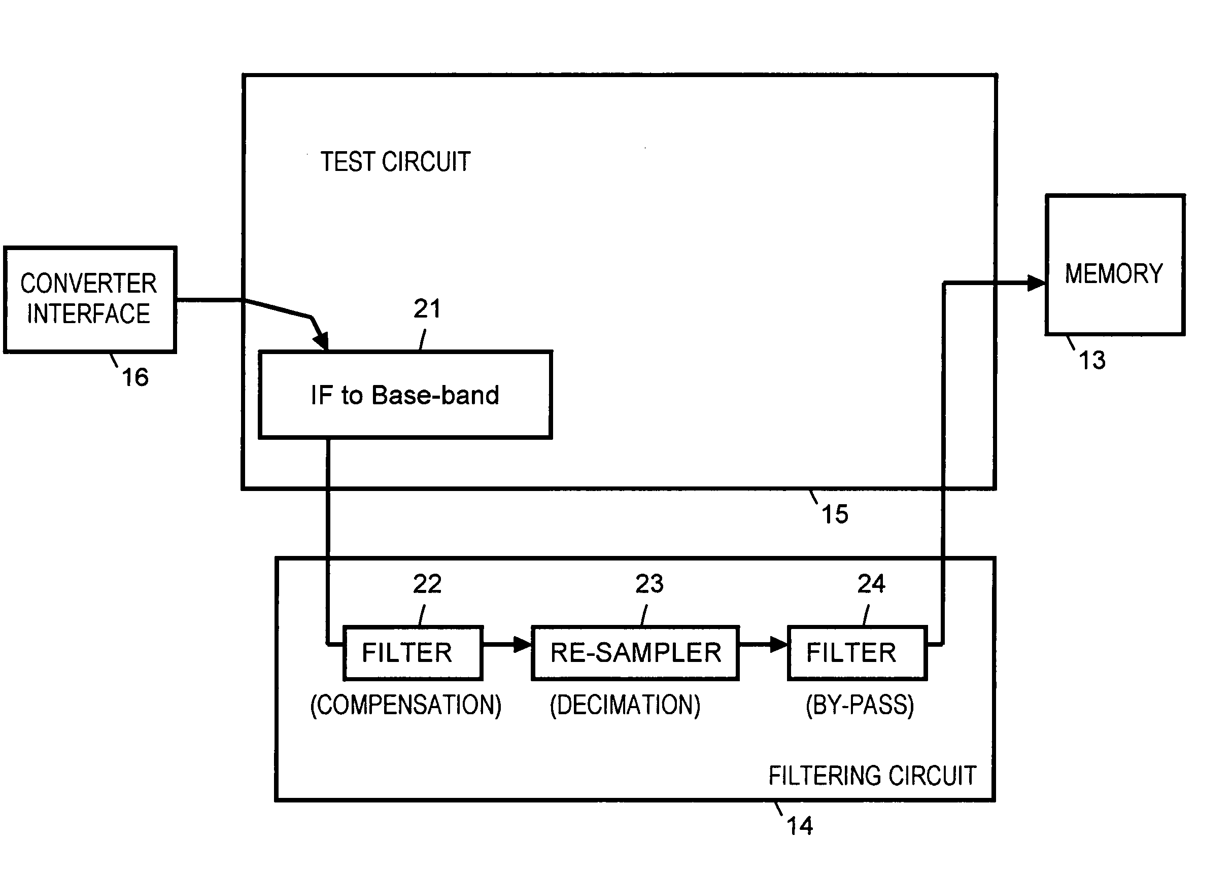
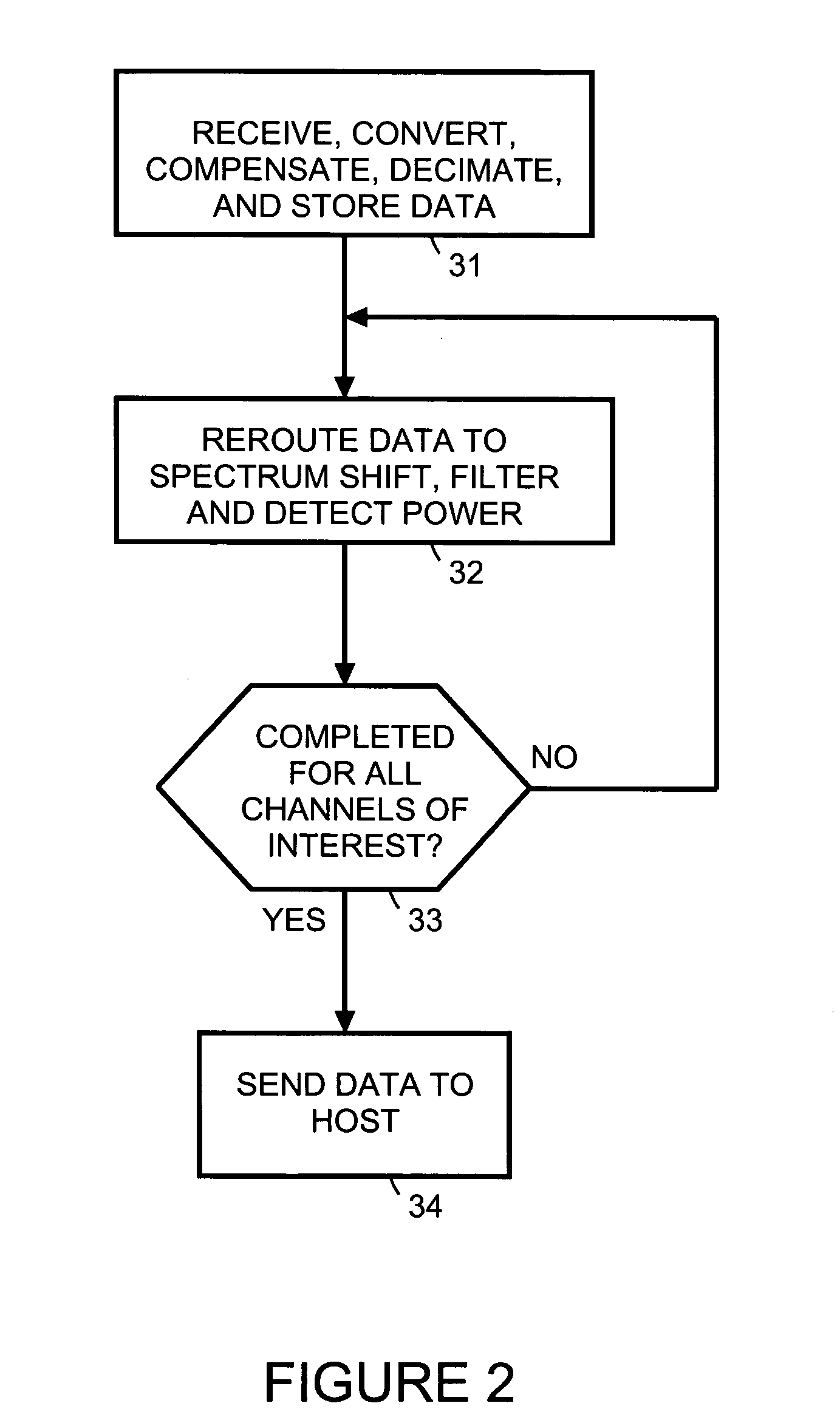
[0007] In accordance with embodiments of the present invention, a tester module is used to perform an adjacent channel leakage ratio measurement. The tester module includes a translation block, a first filter, a re-sampler, a memory, a router, a second filter and a power detector. The translation block translates a received intermediate frequency signal to a baseband signal. The first filter compensates amplitude and phase of the baseband signal for any unflatness in host hardware used to capture the received intermediate frequency signal. The re-sampler decimates the compensated baseband signal. The memory stores the decimated compensated baseband signal. The router reroutes the stored decimated compensated baseband signal to the re-sampler. The re-sampler resamples the rerouted stored decimated compensated baseband signal to perform spectrum shifting. The second filter performs a low pass filtering operation on the resampled rerouted stored decimated compensated baseband signal. The power detector detects channel power of the filtered resampled rerouted stored decimated compensated baseband signal.

Problems solved by technology

This typically results in lower measurement speed.
Each LO retuning takes about 5 milliseconds (ms), which is a relatively long time.
Second, the speed of the FFT and RRC filter operation is limited by the host CPU.
Third, data transfer from a data capture memory to the host is time consuming.

Method used


Image

  • Hardware assisted adjacent channel leakage ratio measurement
  • Hardware assisted adjacent channel leakage ratio measurement
  • Hardware assisted adjacent channel leakage ratio measurement

Examples


Embodiment Construction

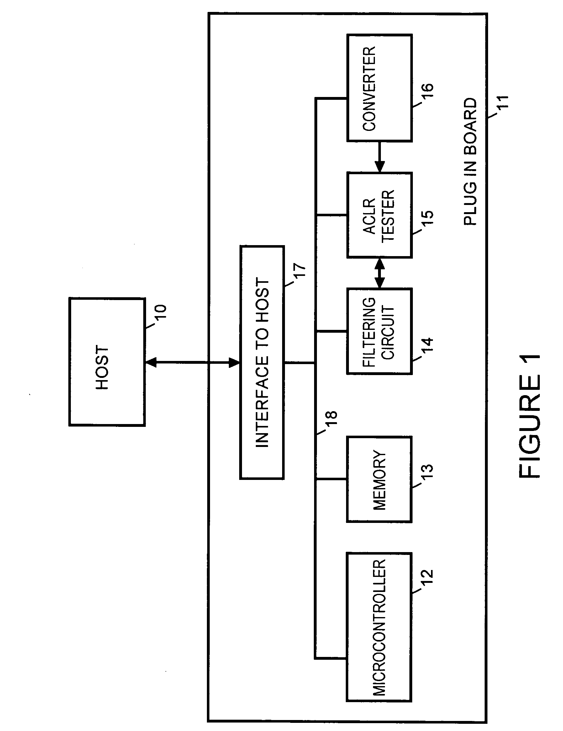
[0012]FIG. 1 is a simplified block diagram of a test module added to a host system10. For example host system 10 is a spectrum analyzer system such as an Agilent PSA series High-Performance Spectrum Analyzer, available from Agilent Technologies, Inc. Alternatively, host system 10 is some other type of analyzer system such as a vector signal analyzer. The test module is, for example, implemented as a daughter board for use by host system 10.

[0013] The test module includes a host interface 17, a microcontroller 12, memory 13, a filtering circuit 14, a tester circuit 15 and a converter interface 16 connected via a bus 18.

[0014] For example, host interface 17 is a peripheral component interconnect PCI bus standard compatible interface. Microcontroller 12 is, for example, implemented using a PowerPC compatible reduced instruction set computer (RISC) microprocessor available from IBM or Motorola, Inc.

[0015] For example, converter interface 16 receives from host system 10 hardware inter...


PUM


Abstract

A tester module is used to perform an adjacent channel leakage ratio measurement. The tester module includes a translation block, a first filter, a re-sampler, a memory, a router, a second filter and a power detector. The translation block translates a received intermediate frequency signal to a baseband signal. The first filter compensates amplitude and phase of the baseband signal for any unflatness in host hardware used to capture the received intermediate frequency signal. The re-sampler decimates the compensated baseband signal. The memory stores the decimated compensated baseband signal. The router reroutes the stored decimated compensated baseband signal to the re-sampler. The re-sampler resamples the rerouted stored decimated compensated baseband signal to perform spectrum shifting. The second filter performs a low pass filtering operation on the resampled rerouted stored decimated compensated baseband signal. The power detector detects channel power of the filtered resampled rerouted stored decimated compensated baseband signal.

Description

BACKGROUND [0001] Adjacent channel leakage ratio (ACLR) is the ratio of power measured in an adjacent channel to transmitted power. In the case of wideband code division multiple access (W-CDMA), both the transmitted power and the adjacent channel power are measured with a filter that has a root raised-cosine (RRC) filter response with rolloff of a =0.22 and a bandwidth equal to the chip rate. [0002] ACLR is one of the most important measurements in the wireless communication industry. Performing ACLR with measurement precision (or repeatability) and speed are important factors when minimizing manufacturing and testing costs for wireless communication devices. [0003] In the case of W-CDMA (also called spread spectrum) manufacturing, the 3GPP specifications require measurements of the power ratios of two adjacent channels (+ / −5 MHz offset from the carrier frequency) and two alternative channels (+ / −10 MHz offset from the carrier frequency) over the carrier channel power. For ACLR, su...

Claims


Application Information

Patent Timeline
Patent Type & Authority Applications(United States)
IPC IPC(8): H04L27/00H04B15/04H04B17/00H04L27/06
CPCH04B15/04H04B17/354H04B2215/067H04B2215/064H04B17/309H04B17/00
Inventor ZHANG, JOE
Owner AGILENT TECH INC
Why Eureka
Eureka Blog
Learn More