Monitoring of flames using optical fibers and video camera vision system

a technology of optical fibers and video cameras, applied in the direction of combustion control, fuel supply regulation, combustion regulation, etc., can solve the problems of large limitation, failure to use, and failure to meet the needs of the user

Inactive Publication Date: 2005-12-01
GANESHAN RAM
View PDF6 Cites 38 Cited by
  • Summary
  • Abstract
  • Description
  • Claims
  • Application Information

AI Technical Summary

Benefits of technology

[0028] The present invention relates to a new technology in the furnace flame detection, both in principle and in the choice of detection equipments. Optical fibers are used to collect the light from several flames from the burners at the furnace end and transmit the light through a desired distance to a video camera box, which is protected from external light sources and located in a safe area and convenient place. Thus the operator at the control center can conveniently and continuously view the “live” images of the glows and the status data on the burners.

Problems solved by technology

They fail frequently if the flame intensity or composition of the fuel fluctuates and / or dust settles on the viewing glass of the scanner.
This is a big limitation.
Oil fired burners, which make a good percentage of burners in the world, cannot use them.
In addition, the sensitivity of the UV scanners reduces with shelf life and the operating life.
The UV scanning technique also presents great difficulty when desired to monitor pilot flames.
Due to the small size of the pilots and their inaccessible locations, great difficulties are encountered in finding a suitable location for the scanner.
But continued exposure to flame and high temperatures leads to thermal degradation leading to extremely short lifespan, typically a few months.
Replacement and even maintenance are difficult since the sensor locations and the insulated mounting arrangements are difficult to access.
Such shutdowns result in high operating costs for the facility.
Thermocouples fail after sometime due to their close proximity to the flame and pose similar difficulties as Flame Rods to access and higher costs.
All the abovementioned flame sensors have the common disadvantage of requiring multiple sensors for multiple burners, since these sensors are capable of monitoring only one flame at a time.
One disadvantage of this method is the unavailability in practice of such view glasses in desirable locations.
A large number of existing furnaces do not have sight ports where the camera can be mounted to view the flames.
Often existing or planned sight ports are not ideally located to view all the burners.
That makes the method difficult to apply especially since installation of a new sight port can be done only when the furnace is shut down.
This difficulty results in continued reliance on less reliable UV detection methods for flame monitoring and control, raising safety concerns.
Even when such maintenance shut down is scheduled, mounting of the camera in a suitable location requires extensive advance planning and significant additional costs in the necessary extension of the shut down period (leading to charges for lost production), as well as in the costs of the modification itself.
They add to the cost in addition to a lot of engineering and planning.
This also increases the system cost considerably.
Additionally, in many cases, the field of the camera does not permit the entire range of burners to be viewed comprehensively and allows viewing only a few burners well.
This will increase the cost and make the controls more complicated.
Another disadvantage of the before mentioned patent is that in many furnaces, such as industrial boilers, code regulations require both the pilot flame and the main flame of all burners to be monitored directly.
A camera directly viewing the flames may find it difficult to distinguish the presence of small pilot behind larger main flame envelopes.

Method used


Image

  • Monitoring of flames using optical fibers and video camera vision system
  • Monitoring of flames using optical fibers and video camera vision system
  • Monitoring of flames using optical fibers and video camera vision system

Examples


Embodiment Construction

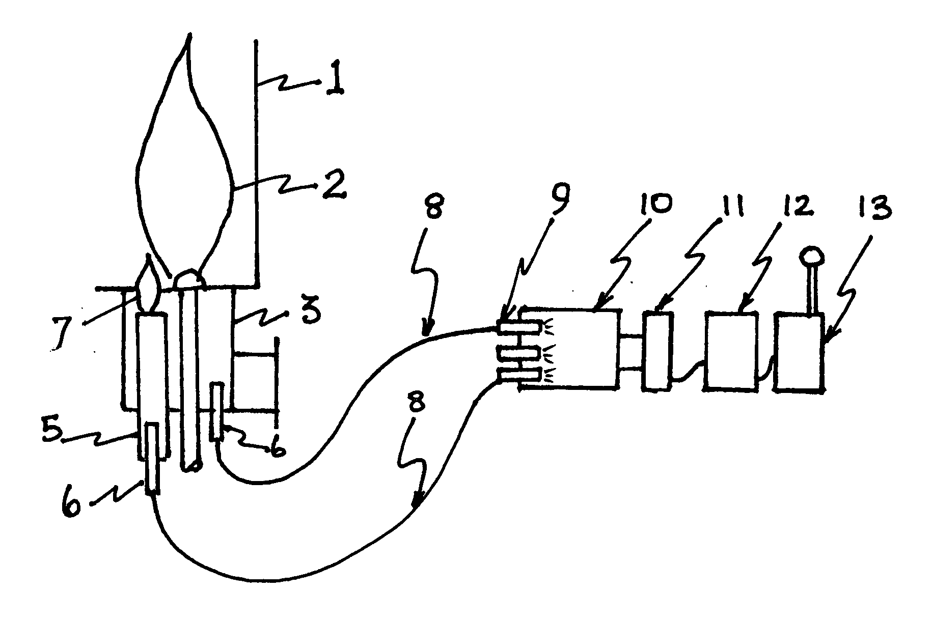
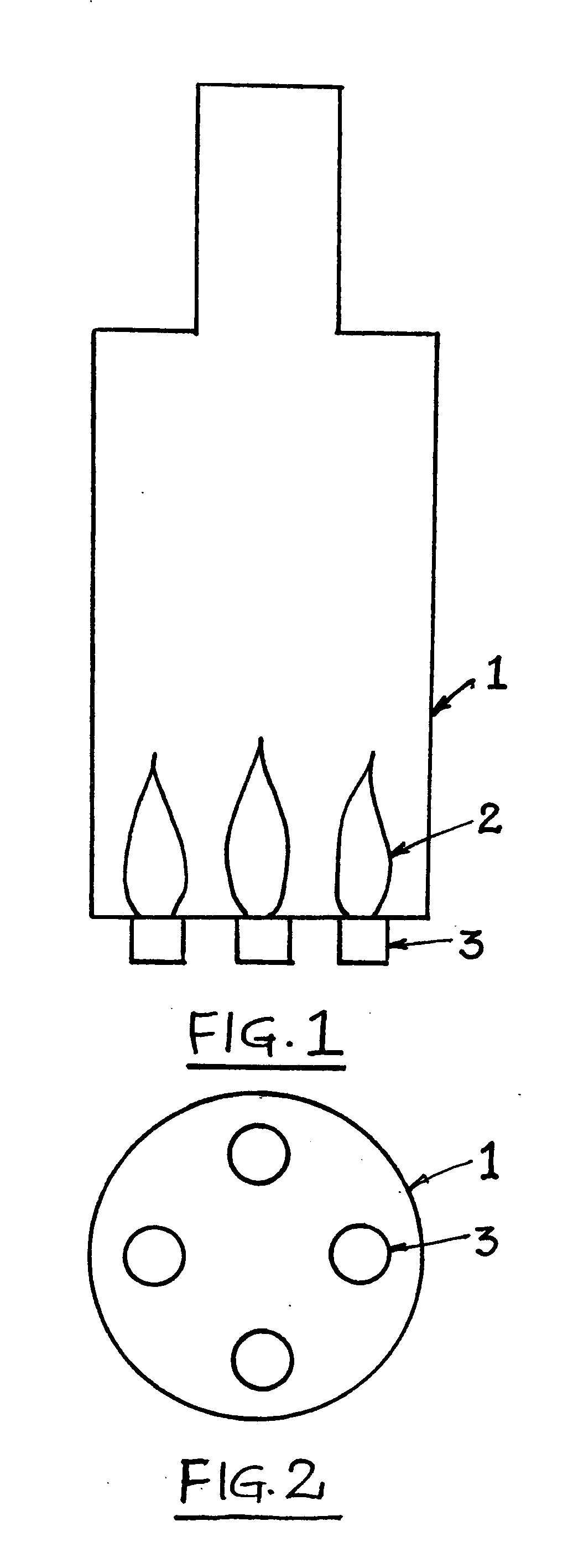
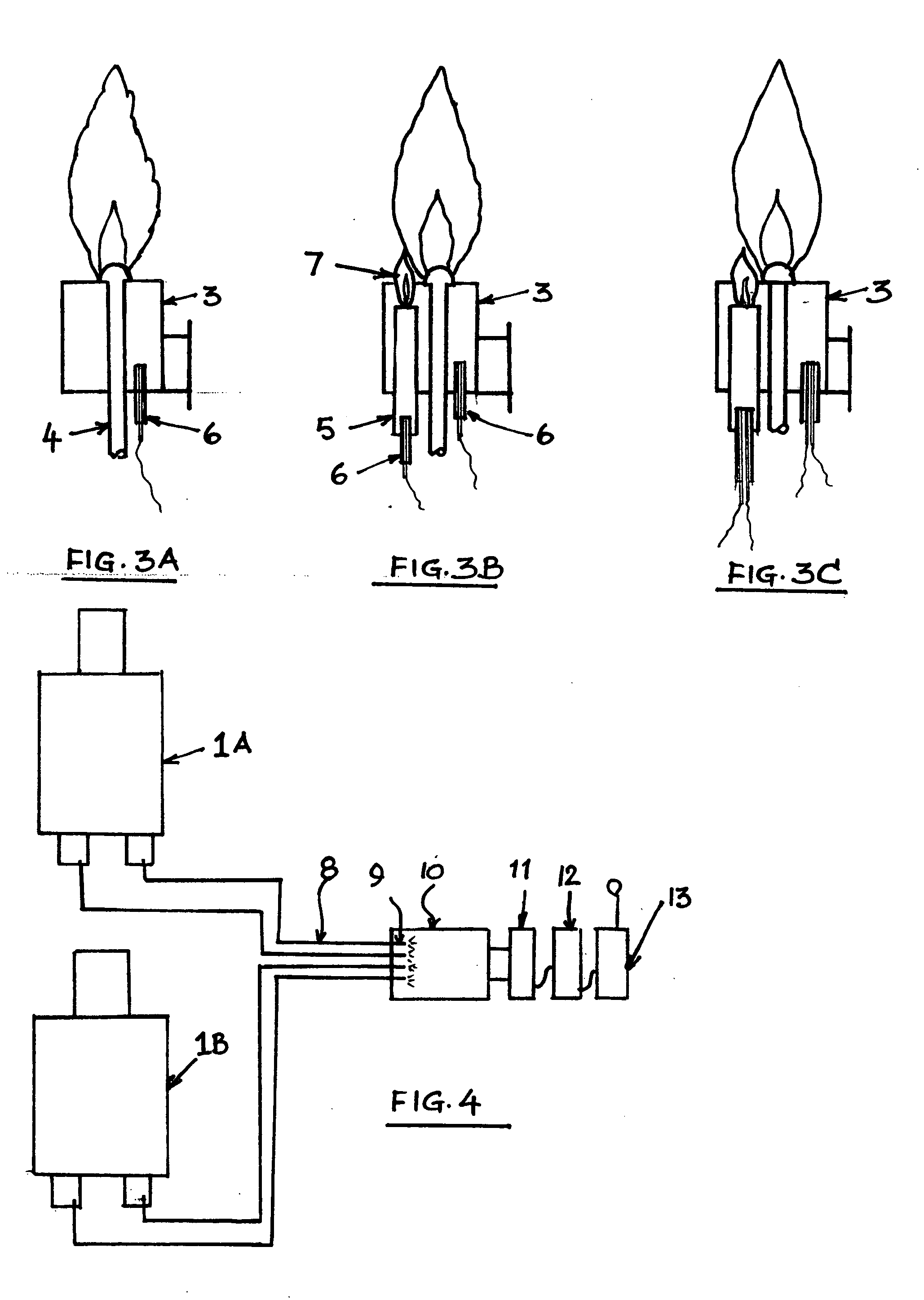
[0039] The light-receiving end of the optical fiber is located at an ideal place in or on the burner housing to view the flame; the tip of the fiber is usually inside a cool air stream. Dust will not collect on the sensing head since there is a constant flow of air across it. The fiber could be made of glass or silicon quartz material, which can withstand high temperatures normally encountered in the furnace. Stainless steel tube sheathing protects the fiber on the sides. Such optical fiber cables are commercially available.

[0040] The flame detection system has several self-checking features. [0041] 1. The fiber bundle inside the cable can have one or more individual fibers. They display individual glows at the other end. When two fibers are used, it will display two distinct dots of glows within the circle at the other end. If one fiber should develop a defect, for example due to a break in the fiber due to long usage, the other fiber will be proving that the flame is on. [0042] 2...


PUM


Abstract

This invention relates to a flame detection method and apparatus. More specifically, this invention relates to a flame d on method and apparatus designed for simultaneously monitoring several flames of different types such as pilot flames and main flames of differing sizes and intensity. These detected flames can be in one combustion unit or in several combustion units such as industrial furnaces or ground flares. The underlying principle of the invention is to collect and transmit light from each of the flames by use of optical fibers and to insect the collected light by a video camera vision system at the other end of the optical fibers and to transmit the “live” images of the glows as well as the “on/off” status of the burners to the control room, through modern electronic communication techniques such as Ethernet and/or wireless radio units.

Description

CROSS REFERENCE TO RELATED APPLICATION [0001] U.S. Pat. No. 6,278,374 B1 [0002] USPTO's Number for the provisional application of this patent: 6052 0535 [0003] Provisional Application filing date: Nov. 17, 2003FEDERALLY SPONSORED RESEARCH [0004] Not applicable SEQUENCE LISTING OF PROGRAM [0005] not applicable BACKGROUND OF THE INVENTION [0006] Heaters, boilers, furnaces, flares, ovens, incinerators, driers, heated baths and other combustion equipment have single or multiple burners. The term furnace will be used in all of the text below to cover all the combustion units mentioned above. Some large heat capacity burners, both gas and oil fired, modulated and fixed capacity, are fitted with smaller heat capacity pilot burners. In many cases both Pilot and the Main flames are continuously monitored for the safety of the furnace. [0007] Well-known flame detection methods are Ultra Violet scanners, thermocouples and flame rods. The currently available flame detection technologies have se...

Claims


Application Information

Patent Timeline
Patent Type & Authority Applications(United States)
IPC IPC(8): F23N1/00F23N5/08
CPCF23N5/082F23N2029/14F23N2037/04F23N2029/20F23N2029/16F23N2229/16F23N2229/20F23N2229/14F23N2237/04
Inventor GANESHAN, RAM
Owner GANESHAN RAM
Why Eureka
Try Eureka