Method for producing a laminate polarizing plate and an optical member using thereof

a technology of optical film and laminate polarizing plate, which is applied in the direction of polarizing elements, instruments, chemistry apparatus and processes, etc., can solve the problems of reducing the contrast by light leakage, generating birefringence, and remarkable increase of the total thickness of optical film disposed on upper and lower liquid crystal cells, etc., to achieve cost reduction, simple production procedures, and simple constitution

Inactive Publication Date: 2005-12-08
SUMITOMO CHEM CO LTD
View PDF17 Cites 22 Cited by
  • Summary
  • Abstract
  • Description
  • Claims
  • Application Information

AI Technical Summary

Benefits of technology

[0013] The inventors of the present invention have diligently studied to develop a laminate polarizing plate which achieves simple constitution, simple production procedures, cost reduction and thin film, for applying to vertical-alignment mode liquid crystal displays to obtain well viewing angle. Besides, the inventors have studied advantageous methods for producing a laminate polarizing plate which is composed of a first phase retarder film being in-plane orientation and a second phase retarder film including a coating layer, like the one disclosed in JP-A No. 2004-4150. Consequently, the inventors have found that a laminate polarizing plate having excellent viewing angle and thin thickness can be produced by transferring and laminating a second phase retarder film comprising a coating layer on a first phase retarder film comprising a transparent resin film having in-plane orientation. Furthermore, when other optical layer is also laminated on the laminate polarizing plate, the obtained one still exhibits excellent optical characteristics; and achieved the present invention.

Problems solved by technology

However, the vertical-alignment mode liquid crystal displays equipping only polarizing plates to a liquid crystal cell, when viewed from inclined directions, remarkably decreases contrast by light leakage due to deviation of viewing angle to the equipped polarizing plates from 90°, and generating birefringence on rod-like liquid crystal molecules in the cell.
Above described methods such that each of a biaxial phase retarder film being independently disposed between a liquid crystal cell and, respective upper and lower polarizing plates, each of an uniaxial phase retarder film and a completely biaxial phase retarder film being independently disposed respectively on and under a liquid crystal cell, or both of an uniaxial phase retarder film and a completely biaxial phase retarder film being co-disposed at one side of a liquid crystal cell, are performed by a complex production procedures or economically disadvantaged, or leading to a remarkable increase of the total thickness of optical film disposed on upper and lower the liquid crystal cell.

Method used


Image

  • Method for producing a laminate polarizing plate and an optical member using thereof
  • Method for producing a laminate polarizing plate and an optical member using thereof
  • Method for producing a laminate polarizing plate and an optical member using thereof

Examples


example 1

[0140] The coating solution was prepared in the following composition.

Acrylic resin varnish “Arontack S1601”10.2%Organic modified clay composite “Lucentite STN”6.75%Organic modified clay composite “Lucentite SPN”2.25%Toluene45.6%Acetone35.2%

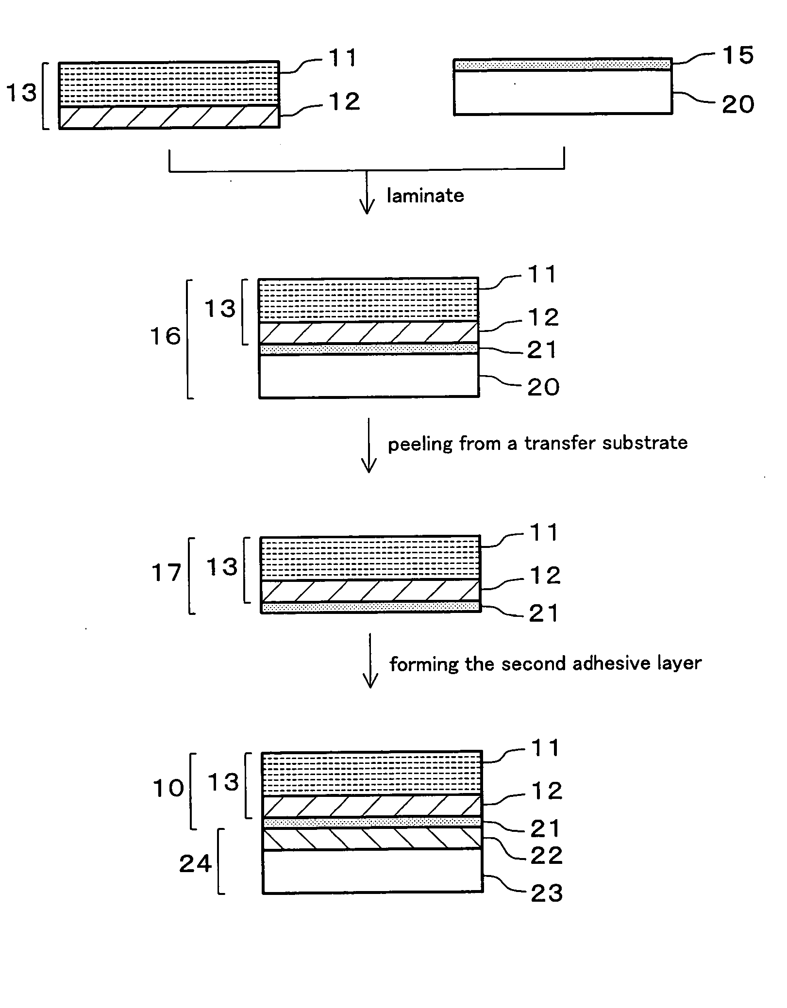
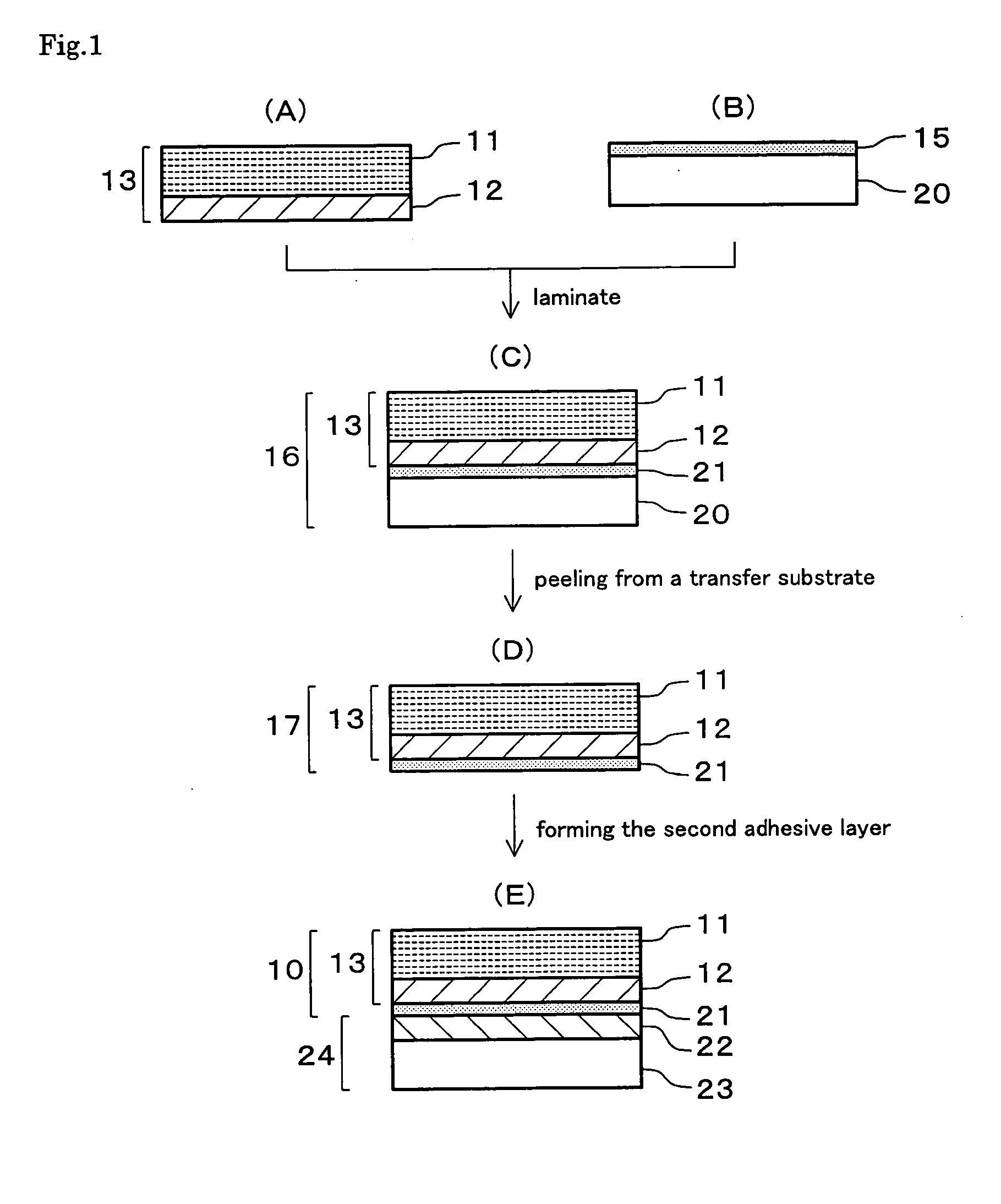
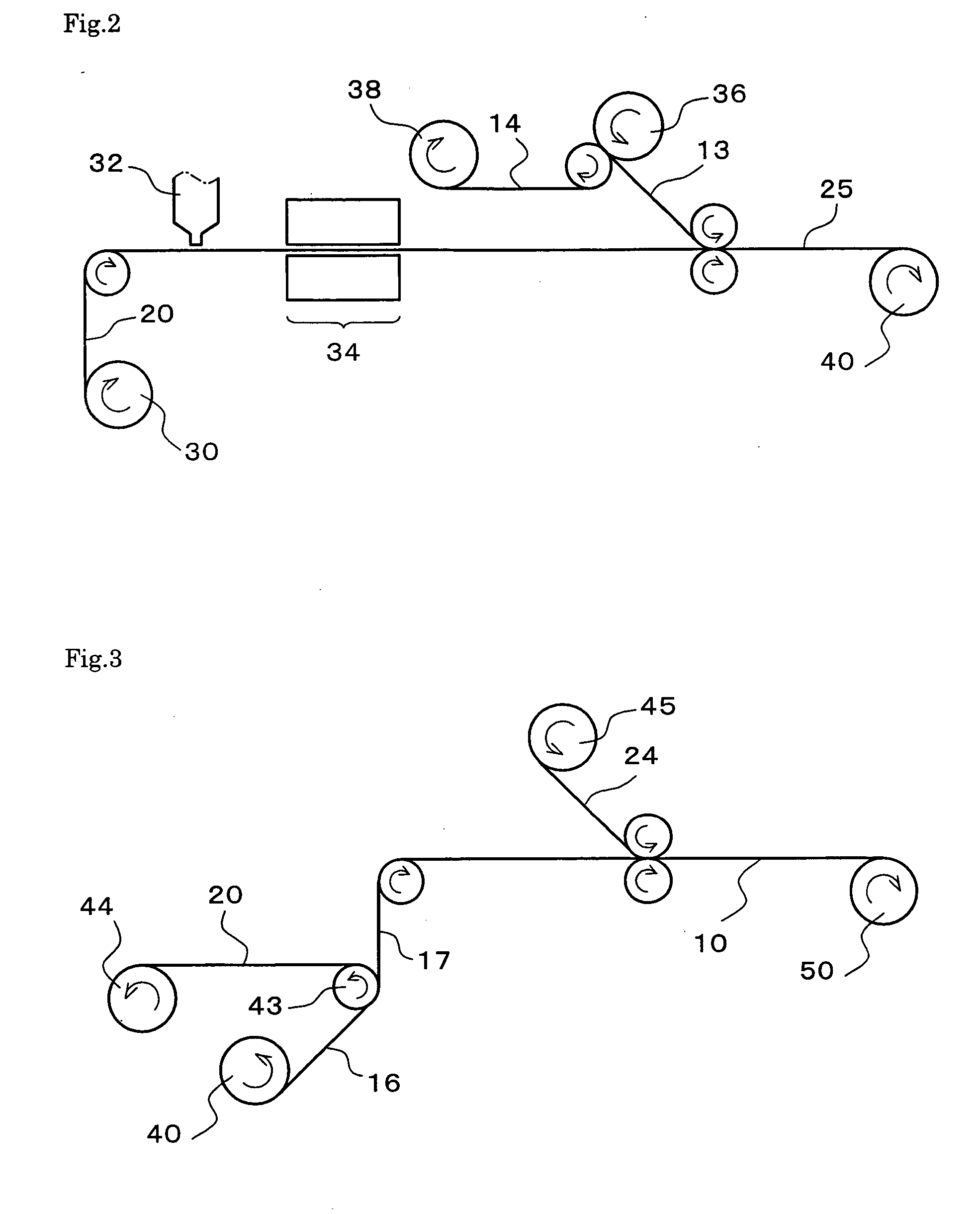
[0141] The prepared coating solution was consecutively coated by a die coater on the polyethylene terephthalate film of 38 μm thickness which had been subjected to mould releasing treatment (the water contact angle at the face of mould releasing treatment was 110°), followed by being subjected to drying during passing through a drying oven; then the coating layer (second phase retarder film) was, at a time just passed out from the oven, consecutively adhered on the exposed surface thereof with the adhesive side of the λ / 4 plate (first phase retarder film, trade name of “Sumikalight SES440138” manufactured by Sumitomo Chemical, R0=138 nm) which is a stretched cyclic polyolefin resin and has an adhesive layer on the one side thereof, and then the...


PUM

PropertyMeasurementUnit
water contact angleaaaaaaaaaa
thicknessaaaaaaaaaa

Abstract

A method for producing a laminate polarizing plate comprising a first phase retarder film and a second phase retarder film, wherein the first phase retarder film comprises an in-plane oriented transparent resin film having an adhesive layer on its surface, the second phase retarder film has at least one coating layer with refractive index anisotropy, and the second phase retarder film is on the adhesive layer is provided. The method comprising: a first step of forming the coating layer on a transfer substrate, followed by laminating an opposite surface of the coating layer to the transfer substrate on the adhesive layer of the first phase retarder film; and a second step of peeling the transfer substrate from the coating layer along with forming a second adhesive layer on the surface of the coating layer from which the transfer substrate has been peeled.

Description

BACKGROUND OF THE INVENTION [0001] 1. Field of the Invention [0002] The present invention relates a laminate polarizing plate effective to improve viewing angle characteristics of liquid crystal displays, a method of producing the same and a liquid crystal display comprising the same. [0003] 2. Description of the Related Art [0004] Liquid crystal displays which have characteristics of low power consumption, low drive voltage, light weight and flat panel, rapidly spread to devices displaying information such as cellular phones, handheld terminals, monitors for computer and televisions. On account of development of liquid crystal cell technologies, liquid crystal displays having various modes are proposed and it is getting to solve the problems of liquid crystal display relating response speed, contrast and narrow viewing angle. The liquid crystal displays, however, are still pointed out on the problem of their narrower viewing angle compared with cathode ray tubes (CRT); hence, vario...

Claims


Application Information

Patent Timeline
Patent Type & Authority Applications(United States)
IPC IPC(8): B32B33/00G02B5/30G02F1/13363
CPCB32B33/00B32B37/203G02F1/13363B32B2307/42G02B5/3083B32B2307/40G02F1/133528
Inventor MATSUOKA, YOSHIKI
Owner SUMITOMO CHEM CO LTD
Why Eureka
Try Eureka