Combustion type waste gas treatment system

a waste gas treatment system and combustion type technology, applied in the direction of combustion types, lighting and heating equipment, incinerator equipment, etc., can solve the problems of affecting the efficiency of the waste gas treatment system, the time of waste gas resident, the waste gas heating scheme, etc., to prevent backfire from spreading

Inactive Publication Date: 2005-12-08
KOMAI TETABUO +10
View PDF17 Cites 11 Cited by
  • Summary
  • Abstract
  • Description
  • Claims
  • Application Information

AI Technical Summary

Benefits of technology

[0007] An object of the present invention is to provide a combustion type waste gas treatment system capable of oxidatively decomposing a hazardous combustible waste gas by heating efficiently with a structure which allows the waste gas to mix with the auxiliary burning gas efficiently without the occurrence of backfire in the waste gas inlet pipe and permits the waste gas to stay in the combustion chamber for a lengthened period of time and which facilitates heating of the waste gas.
[0027] As stated above, at the time of extinguishing the flames, the oxygen gas supply valve and the fuel gas supply valve are closed to stop the supply of the oxygen gas and the fuel gas. Thereafter, the oxygen gas supply line and the fuel gas supply line are supplied with the non-combustible gas as a purge gas in an amount equal to the amount of oxygen gas and fuel gas which would otherwise be supplied. Consequently, it is possible to eliminate variations in the flow rate. Thus, it becomes possible to prevent the occurrence of backfire at the time of extinction of flames.

Problems solved by technology

Conventional waste gas treatment systems of the type described above are not satisfactory in terms of the resident time of waste gas and the scheme of heating waste gas.
In the above-described combustion type waste gas treatment system, because the waste gas is combustible, there is a danger of backfire spreading into a waste gas inlet pipe for introducing the combustible waste gas into the burner part, which may cause devices to be broken.
There is also a danger of pressure rise due to abnormal combustion, which may also cause breakage of devices.
Further, there is a danger that fuel gas or oxygen gas may leak from the fuel gas supply line or the oxygen gas supply line.
When hydrogen gas is used as fuel gas in particular, leakage of hydrogen gas and oxygen gas may cause an explosion.

Method used


Image

  • Combustion type waste gas treatment system
  • Combustion type waste gas treatment system
  • Combustion type waste gas treatment system

Examples


first embodiment

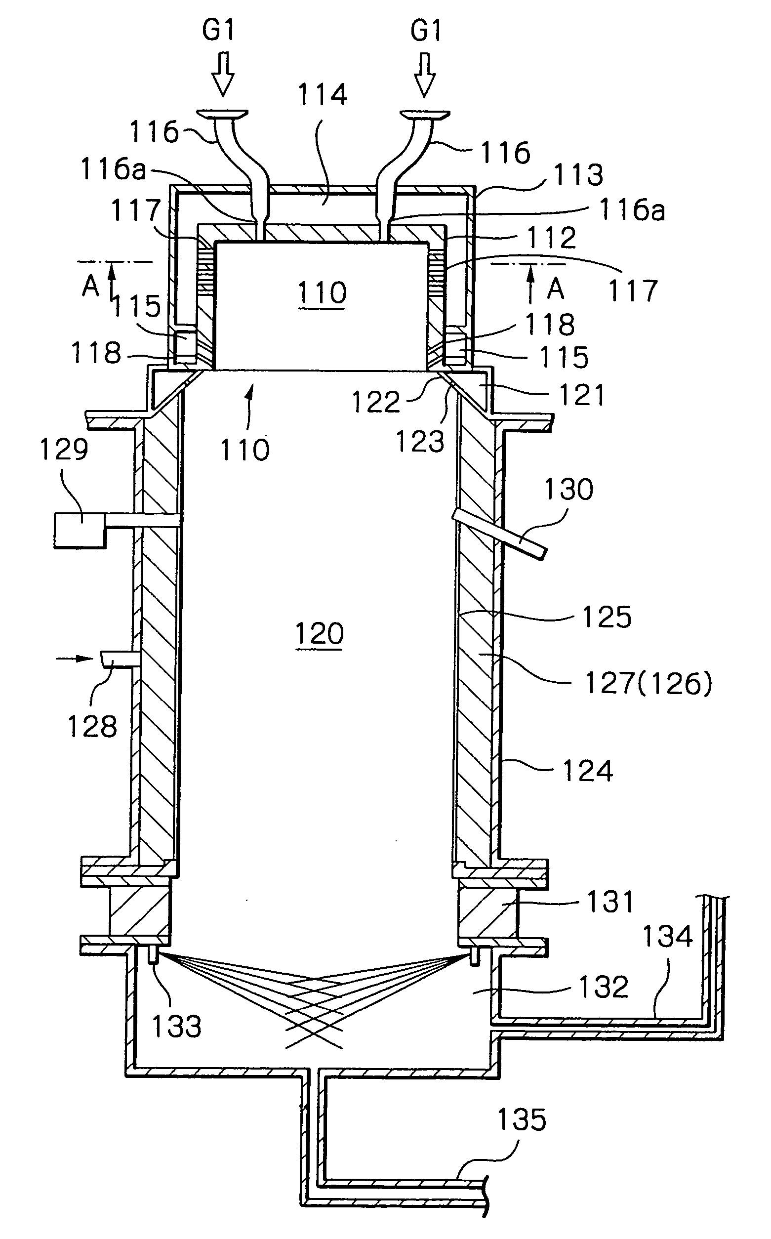
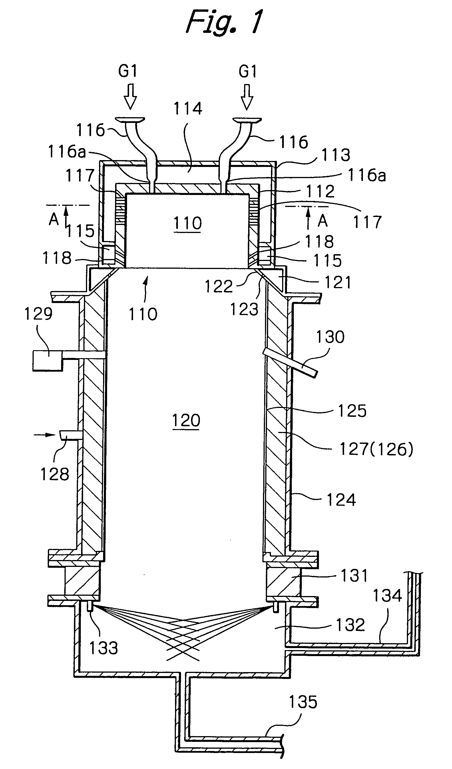
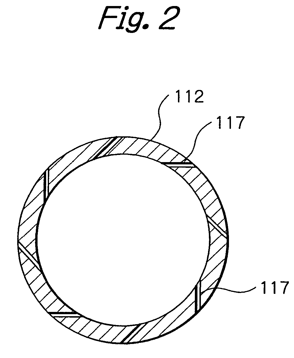
[0046]FIGS. 1 and 2 are diagrams showing the arrangement of the combustion type waste gas treatment system according to the present invention. FIG. 1 is a vertical sectional view, and FIG. 2 is a sectional view taken along the line A-A in FIG. 1. The waste gas treatment system is formed in the shape of a cylindrical closed vessel as a whole. The waste gas treatment system has a burner part 110 in an upper stage and a combustion chamber (combustion reaction part) 120 in an intermediate stage. The waste gas treatment system further has a cooling part 131 and a discharge part 132 in a lower stage. As a cooling medium in the cooling part 131, for example, a liquid, e.g. water, or a gas, e.g. air, is used.

[0047] The burner part 110 has a cylindrical member 112 forming a flame stabilizing portion 111 opening toward the combustion chamber 120. The burner part 110 further has an outer cylinder 113 surrounding the cylindrical member 112 with a predetermined space therebetween. Between the cy...

second embodiment

[0063]FIGS. 10 and 11 are diagrams showing the arrangement of the combustion type waste gas treatment system according to the present invention. FIG. 10 is a sectional view taken along the line E-E in FIG. 11. FIG. 11 is a sectional view taken along the line D-D in FIG. 10. In FIGS. 10 and 11, the same reference numerals as those in FIGS. 1 and 2 denote the same or corresponding portions or members. The combustion type waste gas treatment system according to this embodiment differs from that shown in FIGS. 1 and 2 in that the waste gas inlet pipes 116 are installed on the top of the burner part 110 so that waste gas blown off from openings 116d of the waste gas inlet pipes 116 that open on the inner wall surface of the cylindrical member 112 constituting the burner part 110 forms swirling flows directed obliquely downward in the burner part 110 and the combustion chamber 120.

[0064] As a result of installing the waste gas inlet pipes 116 so that waste gas blown off from the openings ...

third embodiment

[0067] the present invention will be described below with reference to FIGS. 12 to 16. FIG. 12 is a diagram showing a structural example of the combustion type waste gas treatment system according to the present invention. In the figure, arrows A and A, arrows B and B, and arrows C and C are connected together, respectively. In this combustion type waste gas treatment system, hydrogen (H2) gas is used as a gas for combustion. Oxygen (O2) gas is mixed with the hydrogen gas to form combustion flames. Waste gas is introduced into the combustion flames to oxidatively decompose the waste gas. In FIG. 12, a waste gas treatment system body 10 has a burner part 11 and a combustion chamber 12 at the downstream side of the burner part 11.

[0068] An air chamber 13 for holding air (Ae) for combustion is provided around the upper part of the outer periphery of the burner part 11. A fuel gas chamber 14 for holding a mixed gas of hydrogen H2 and oxygen O2 is provided around the middle part of the o...


PUM


Abstract

A combustion type waste gas treatment system capable of oxidatively decomposing a hazardous combustible waste gas while heating efficiently with a structure which allows the waste gas to mix with an auxiliary burning gas efficiently without the occurrence of backfire in a waste gas inlet pipe. The combustion type waste gas treatment system has a burner part and a combustion chamber. Combustion flames are formed to extend from the burner part toward the combustion chamber, and a combustible waste gas is introduced into the combustion flames from waste gas inlet pipes thereby oxidatively decomposing the waste gas. A flow velocity accelerating device makes the flow velocity of the combustible waste gas flowing through the waste gas inlet pipe higher than the burning velocity of the combustible waste gas.

Description

[0001] This application is a divisional of U.S. application Ser. No. 09 / 962,117, filed Sep. 26, 2001, now allowed.BACKGROUND OF THE INVENTION [0002] The present invention relates to a combustion type waste gas treatment system for combustion-treating hazardous and combustible waste gases discharged from semiconductor manufacturing systems, liquid crystal panel manufacturing systems, etc. More specifically, the present invention relates to a combustion type waste gas treatment system for combustion-treating hazardous and combustible waste gases containing, for example, silane gas (SiH4) or a halogen-containing gas (NF3, CF3, SF6, CHF3, C2F6, CF4, etc.), or hardly decomposable waste gases. [0003] A conventional combustion type waste gas treatment system has a burner part and a combustion chamber provided at the downstream side of the burner part. An auxiliary burning gas is supplied into the burner part and burned to form flames, and a hazardous and combustible waste gas introduced in...

Claims


Application Information

Patent Timeline
Patent Type & Authority Applications(United States)
IPC IPC(8): F23J15/02A62C99/00F23G5/32F23G7/06F23L7/00
CPCF23C5/32F23D14/04F23G5/32F23G7/065F23G2209/142F23L7/007Y02E20/344Y02E20/34F23J15/02
Inventor KOMAI, TETSUOKAWAMURA, KOHTAROTSUJI, TAKESHINAKAMURA, RIKIYAOKUDA, KAZUTAKAISHIKAWA, KEIICHIOHASHI, TOMONORITAKEMURA, YOSHIROMUROGA, YASUTAKANISHIKAWA, TADAKAZUSHIRAO, YUJI
Owner KOMAI TETABUO
Why Eureka
Try Eureka