Collapsible cover for seating unit

Active Publication Date: 2005-12-15
6134548 CANADA
View PDF34 Cites 20 Cited by
  • Summary
  • Abstract
  • Description
  • Claims
  • Application Information

AI Technical Summary

Benefits of technology

[0048] In another aspect of the invention, is the cover is adapted to be mounted on an infant seat such that the opposing ends are releasably held to the foot and head position of the infant seat by means of the previously described peripheral skirt, which can uninterruptedly surround the continuous perimeter of the infant seat so as to provide stable attachment of the cover frame member to the head a

Problems solved by technology

Although this design does not require a canopy for ceiling support, it has limited collapsibility, as its spring rod members are normally straight and rigid, thereby requiring them to be forced into a coiled shape.
Apart from not covering the legs of the stroller occupant, this shade does not disclose rain or insect protection.
While this design allows for unobtrusive positioning of the sun visors, the sun visors disclosed are not intended for interchangeability with incompatible or dissimilar seats.
This cover can only be used on infant carrier seats that come with handles.
In addition, this cover cannot be used when the handle is stowed for transport in an automobile, which is a normal requirement for fastening car seats with rotating handles into automobiles.
Apart from not coving the legs of the stroller occupant, this shade does not disclose rain or insect protection.
In addition, the small side section surface area that results from the geometry of this cover reduces the overall volume of space available to the occupant, which has the potential of causing distress to the infant due to feelings of confinement.
In practice, this technique of accessing the infant is impractical when one considers that removing the elastic from one edge removes tension from the entire cover perimeter seal, which has the effect of collapsing the ceiling, thereby requiring complete removal or temporary stowing of the cover so that it can be out of the way for access to the infant.
Although good for extremes of pollution, this design relies primarily upon self-powered mechanical ventilation rather than natural ventilation.
This method of maintaining the arched configuration, although feasible for a tent is not amenable to other applications in which the side panel lower edges must remain flexible for attachment to seating devices.
This twisting procedure for collapsing results in the collapsed tent fabric being turned inside out, resulting in a tangled collapsed tent that is often time consuming to disentangle and deploy during the self erecting process.
This hourglass shaped tent is not particularly amenable to applications where the ceiling sur

Method used


Image

  • Collapsible cover for seating unit
  • Collapsible cover for seating unit
  • Collapsible cover for seating unit

Examples


first embodiment

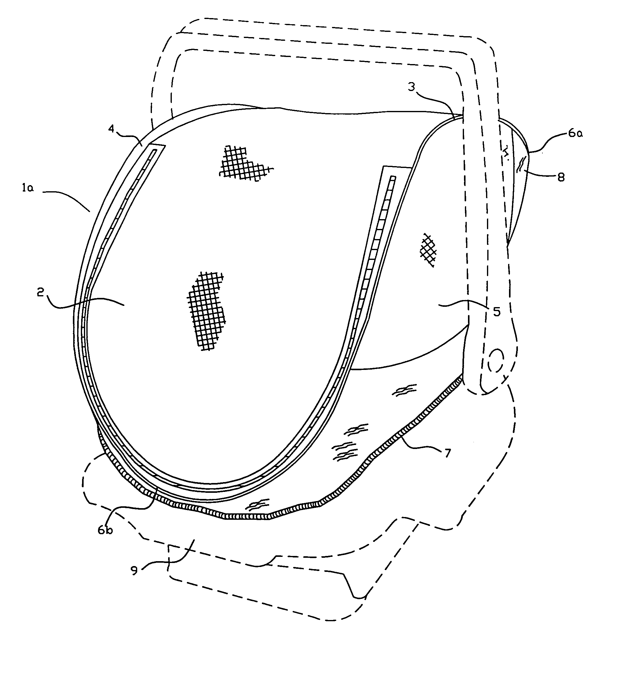
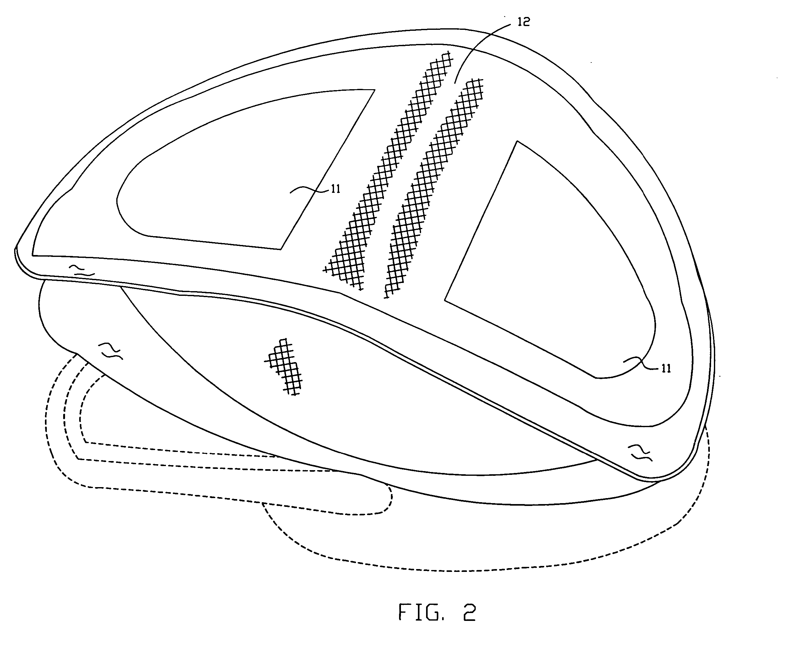
[0081]FIG. 2 illustrates a minimal configuration of the first embodiment, which has a top opening to allow for access to the occupant of the seat. In the embodiment of FIG. 1, two top openings 11 are provided with a center web therebetween to help in maintaining stability which is further enhanced by means of reinforced side panel membranes. In the preferred embodiment, FIG. 3 illustrates an example of a top opening 13, which is closable by means of zipper flap 14 and optionally tied back by means of a tie 15 or other such methods as is known to those familiar with the art. In another embodiment, FIG. 4 shows the top opening 13 closable by means of elasticized flap 16 and secured from inadvertent removal by means of button or snap 17 at the head 6a and foot 6b. The ability to open the cover wide enough to allow access to the occupant of the protective cover is afforded by the large minor axis, or width of the elliptically shaped ceiling membrane, due in part to the frame member loop...

third embodiment

[0089] Referring to FIG. 5a, the head 6a of the frame member 3 is secured to the carriage head position 8 by means of an elasticized strap 19. This elasticized strap 19 can be easily slid around the carriage pusher posts 26 thereby effectively clamping the head 6a of the frame member 3 against the carriage pusher posts 26. A friction padding 27 made of rubberized material or the like can be effectively employed along an appropriate length of the head 6a in order to minimize slippage of the frame member 3 against the pusher posts 26. The elasticized strap 19 can be permanently stitched to the head 6a of the frame member 3 or fastened by means of a snap or button 17 or other such method as is common to those familiar with the art. The elasticized strap 19 can be replaced by an adjustable webbing material, cording, tube clips, clamps or other such means that achieves the desired clamping effect. Although not depicted, these features are equally applicable to embodiment second as to the...


PUM


Abstract

The present invention is directed to a collapsible cover for protecting an occupant in a seating unit having a head region and a foot region. The cover has a body comprised of a flexible material having a top portion and at least one side wall portion, the top portion having a generally ellipse shape and having a length to span the distance between the head region and foot region of the seating unit and a width to span the width of the seating unit. The sidewall portion is connected to the top portion along a substantial portion of the periphery of the top portion to provide an arched configuration to the top portion. The cover further has a single closed loop frame member made of a flexible, coil-able, resilient material, that is secured along the length of the structure's membrane body so as to assume an ellipse-like shape when viewed from above, that is bent into an arched configuration about its minor axis. The closed loop frame member is movable between an extended orientation to allow the cover to be attached to the seating unit and a collapsed orientation to allow for a reduced size of the cover for transport and storage and is connected to the periphery of the top portion to provide in the extended orientation an arched ellipse shape about the length of the top portion. The cover also has a means for releasably attaching the cover to a seating unit

Description

CROSS REFERENCE TO RELATED APPLICATIONS [0001] This application is a continuation of Ser. No. 60 / 579,260 filed Jun. 15, 2004.FIELD OF THE INVENTION [0002] The present invention relates to accessories for seating devices. More specifically, it relates to a protective cover that is multi-purpose, and easily deploys and collapses for use on a variety of seating devices. BACKGROUND OF THE INVENTION [0003] For many years manufacturers have addressed the need for protective enclosures for seating devices that protect the occupant from hazards such as sun, wind, rain, snow, cold, blowing sand, insects, contact by strangers, saliva aerosol, cold, moderate and tropical climates, and the like. Protective covers have been designed to provide for a total encapsulation of the occupant, while considering the importance of ventilation, that the cover can be interchangeably affixed to a variety of seating device types and models, that the cover be easily removed, that it installs and removes quickl...

Claims


Application Information

Patent Timeline
IPC IPC(8): B62B9/14B60N2/44B60N2/28A47C31/11A47C7/66A47C31/00B60N2/60B60N2/58A47D1/10A47D15/00A47C1/08A47C7/62B62B9/00B60N2/90
CPCB60N2/2842B60N2/6009B62B9/142
Inventor MCGREGOR, ROB ROY
Owner 6134548 CANADA
Why Eureka
Try Eureka