Pneumatic valve control using downstream pressure feedback and an air turbine starter incorporating the same

a technology of pneumatic valve and feedback, which is applied in the direction of fluid pressure control, liquid fuel engines, instruments, etc., can solve the problems of affecting the opening performance affecting the operation and leaking past the actuator piston, so as to improve the opening characteristics of the starter air valv

Active Publication Date: 2005-12-15
HONEYWELL INT INC
View PDF22 Cites 31 Cited by
  • Summary
  • Abstract
  • Description
  • Claims
  • Application Information

AI Technical Summary

Benefits of technology

[0006] The present invention provides a pneumatic valve assembly including a control that uses downstream pressure feedback to provide improved valve opening characteristics as compared to presently known valve assemblies, and that compensates for certain types of leakage within the actuator.

Problems solved by technology

Although these present actuators generally operate safely and effectively, the actuators can suffer certain drawbacks.
For example, the piston seal (or diaphragm) can wear and cause some leakage past the actuator piston.
This leakage can potentially degrade the opening performance of the starter air valve.
In some cases, if the leakage becomes great enough, the actuator may be unable to open the starter air valve.

Method used


Image

  • Pneumatic valve control using downstream pressure feedback and an air turbine starter incorporating the same
  • Pneumatic valve control using downstream pressure feedback and an air turbine starter incorporating the same
  • Pneumatic valve control using downstream pressure feedback and an air turbine starter incorporating the same

Examples


embodiment 300

[0048] The remaining portion of this starter air valve embodiment 300 that differs from the previous embodiment is the bleed flow passage 306. The bleed flow passage 306 is fluidly coupled between the actuation control valve housing outlet flow passage 282 and the rate control servo mechanism housing control air inlet flow passage 244. In particular, the bleed flow passage includes an inlet port 340 that is fluidly coupled to both the actuation control valve housing outlet flow passage 282 and the rate control servo mechanism housing control air inlet flow passage 244, and an outlet port 342 that is vented to the surrounding environment. A bleed orifice 344 is disposed within the bleed flow passage 306, and restricts the flow of pressurized air through the bleed flow passage 306. The bleed orifice 344 is sized to not only limit pressurized air flow through the bleed flow passage 306, but additionally ensures that the pressure downstream of the regulator housing outlet flow passage 3...

embodiment 200

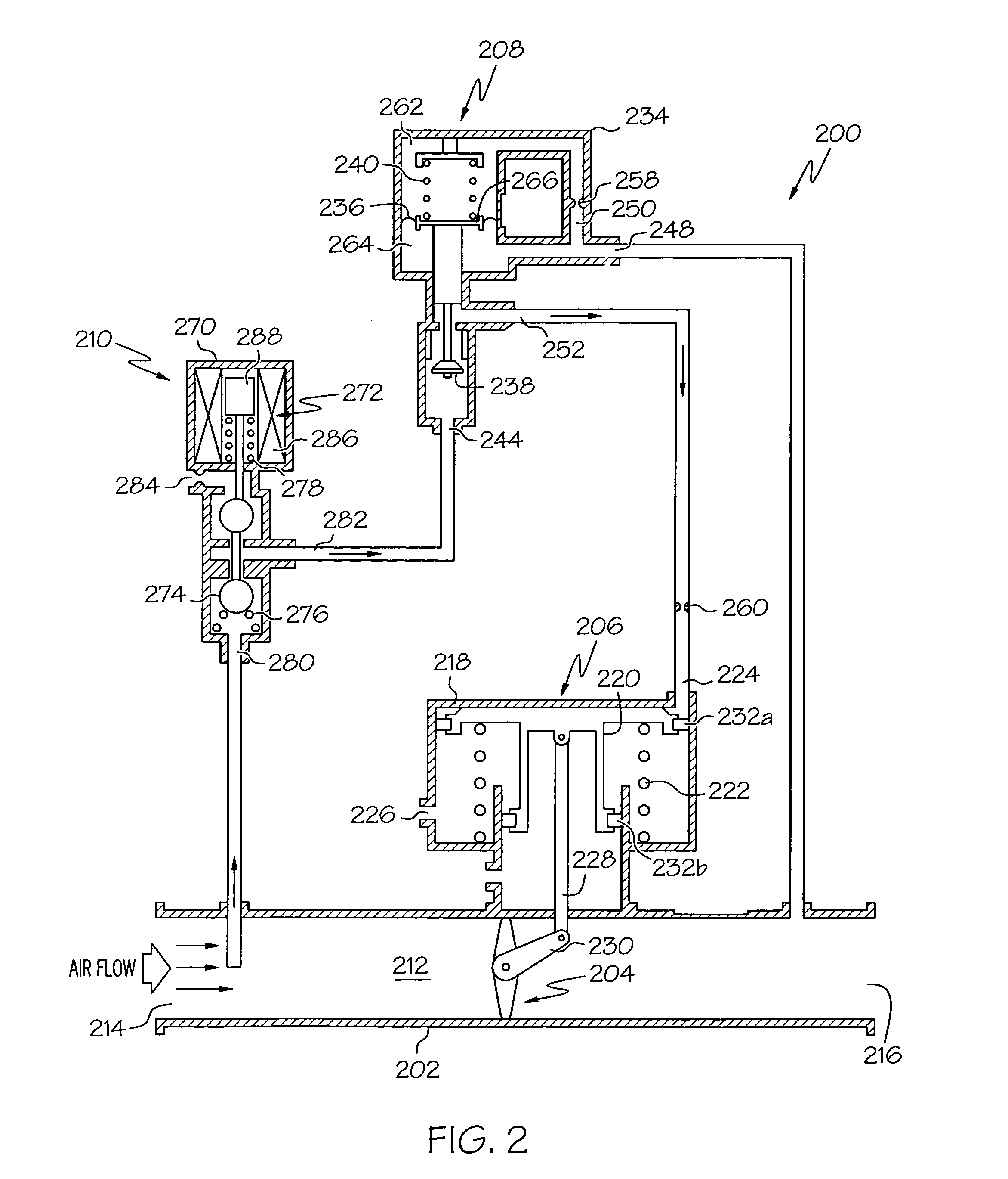
[0055] When it is desired to close the starter air valve 300, its operation is similar to that of the previously described embodiment 200. In particular, the actuation control valve solenoid 272 is first de-energized, which allows the solenoid bias spring 278 and the valve bias spring 276 to move the valve 274 to the first position. With the valve 274 in the first position, the bleed flow passage 340 is fluidly isolated from the reference regulator 302. However, the bleed flow passage 340 and actuation control valve vent port 284 remain fluidly coupled to the rate control servo mechanism housing control air inlet flow passage 244. Because the poppet valve 238 is biased toward its open position, the control air outlet flow passage 252 and thus the actuator housing 218 are fluidly coupled to the bleed flow passage 340 and vent port 284. Thus, the regulated control air in the actuator housing 218 is vented to atmosphere via the bleed flow passage 340 and vent port 284. This releases th...


PUM


Abstract

A starter air valve assembly includes a valve body, a flow control valve, a rate control servo mechanism, and a valve actuator. The valve body defines a flow passage having at least an inlet port and an outlet port. The valve is disposed at least partially within the flow passage and is moveable between an open position and a closed position. The rate control servo mechanism is adapted to receive pressurized fluid and is configured, upon receipt of the pressurized fluid, to supply a controlled flow of the pressurized fluid. The valve actuator is coupled to the valve and is in fluid communication with the rate control servo to thereby receive the controlled flow of the pressurized fluid. The valve actuator is configured, upon receipt of the controlled flow of the pressurized fluid, to move the valve between the closed position and the open position at a substantially controlled rate.

Description

TECHNICAL FIELD [0001] The present invention relates to pneumatically actuated valves and, more particularly, to a pneumatically actuated starter air valve that uses downstream pressure feedback to provide improved opening characteristics. BACKGROUND [0002] Many relatively large turbine engines, including turbofan jet engines, may use an air turbine starter (ATS) to initiate turbine engine rotation. The ATS may be mounted by the engine, much as a starter for an automobile is located by the automobile engine. The ATS may be coupled to a high pressure fluid source, such as compressed air, which impinges upon a turbine wheel in the ATS causing it to rotate at a relatively high rate of speed. The ATS includes an output shaft that is coupled to the turbine wheel and, perhaps via one or more gears, to the jet engine. The output shaft thus rotates with the turbine wheel. This rotation in turn causes the jet engine to begin rotating. The applicant for the present invention, Honeywell Intern...

Claims


Application Information

Patent Timeline
Patent Type & Authority Applications(United States)
IPC IPC(8): F01B25/02F01D17/14F02C7/277F02C9/20F16K31/36F16K31/42G05D16/16
CPCF01D17/145F02C7/277F02C9/20F05D2260/85F16K31/42G05D16/166F16K31/36Y10T137/777Y10T137/7762
Inventor WIGGINS, JIMMY D.BANTA, PAUL W.WOODRUFF, EDWARD E.
Owner HONEYWELL INT INC
Why Eureka
Try Eureka