Magnetic clasp apparatus

a technology of magnetic clasps and apparatuses, which is applied in the direction of bracelets, wristwatch straps, press-button fasteners, etc., can solve the problems of loss or anxiety about loss, poor quality of magnetic clasps, and easy disengagement of clasps accidentally, so as to reduce magnetic flux, increase structural resistance, and facilitate the effect of taking o

Inactive Publication Date: 2005-12-22
DUNAYE GARY
View PDF12 Cites 21 Cited by
  • Summary
  • Abstract
  • Description
  • Claims
  • Application Information

AI Technical Summary

Benefits of technology

[0011] In another embodiment, a steel tube is positioned in the bore of one section to encase the magnets to redirect magnetic flux and provide additional structural resistance against opposing force through the eyelets. Additional steel shielding can be used to reduce magnetic flux emanating from the clasp. In a preferred embodiment the clasps use neodymium magnets-the strongest magnets available.
[0012] The tube is designed to create a vertical chamber when the two magnets are together, and locks perpendicular to the horizontal force of the bracelet or necklace. The interlocking camber design also aids in the ease of removing the clasp sections.
[0013] A fairly large force is needed to overcome the attractive force of the magnets to separate the sections of the clasp. To this end a lifting or cambering action is used. By turning one of the clasp sections counterclockwise, the camber edge thus elevates against its mate, therefore separating the upper and lower magnets and consequently separating the top section from the bottom section. Because of the 90 degree end, or stop of each camber, a clockwise rotation is prevented. The overall effect is a controlled, even force upward, easily performed by anyone.
[0014] The interlocking camber design of the present invention prevents horizontal, vertical, and clockwise movement. The invention is easy to put on, ea

Problems solved by technology

Most magnetic clasps use poor quality magnets and are designed to be pulled apart by applying opposing force through the eyelets.
These clasps are easily disengaged accidentally because there is no structure to resist the opposing forces on the eyelets-just the magnetic force of the magnets.
Accidenta

Method used


Image

  • Magnetic clasp apparatus
  • Magnetic clasp apparatus
  • Magnetic clasp apparatus

Examples


Embodiment Construction

[0051] Referring more specifically to the drawings, for illustrative purposes the present invention is embodied in the apparatus generally shown in FIG. 1 through FIG. 7. It will be appreciated that the apparatus may vary as to configuration and as to details of the parts, and that the method may vary as to the specific steps and sequence, without departing from the basic concepts as disclosed herein.

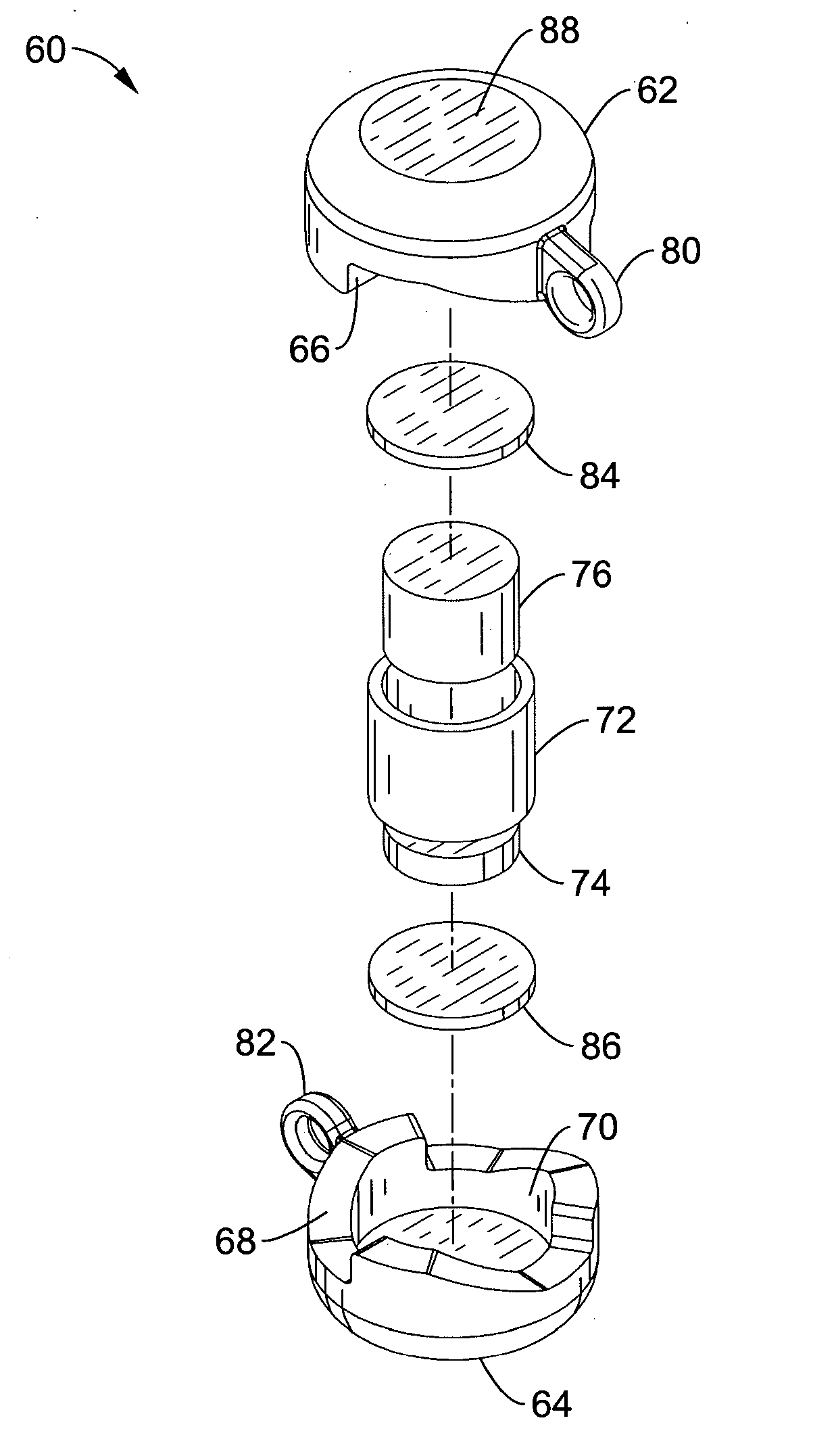
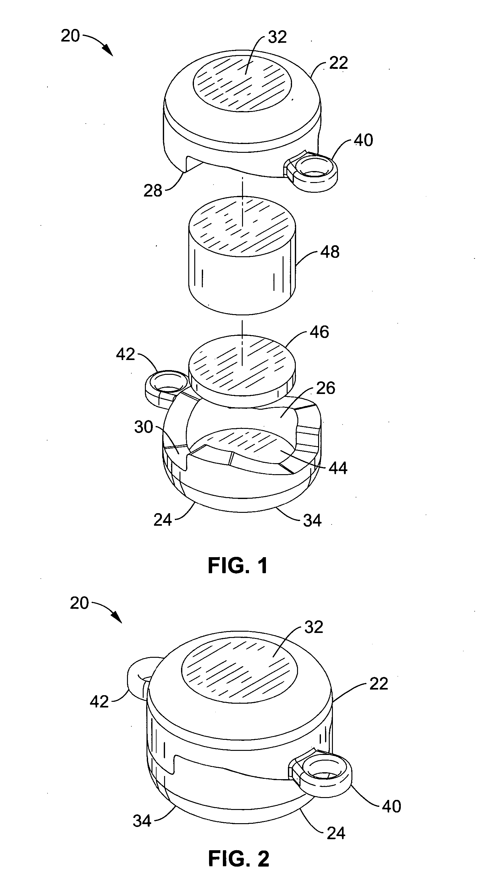
[0052]FIG. 1 illustrates an exploded perspective view of a clasp 20 in accordance with the present invention. Clasp 20 generally comprises a top section 22 and a bottom section 24 of a material with no magnetic properties, such as sterling silver, bronze, gold or other precious metal or jewelry metal alloy. Other materials such as aluminum, copper, stainless steel, ceramic or plastic may be suitably used in some applications. These materials may be plated or coated with a precious metal or jewelry metal alloy. Top and bottom sections 22, 24 are generally opposing cylinders having a bor...


PUM


Abstract

A jewelry clasp with top and bottom sections, each section having a bore to receive a magnet, and each section having an interlocking surface on the perimeter of the bore. An eyelet is positioned on the perimeter of each section. The interlocking surfaces consist of mating camber protrusions that will lift and separate the top and bottom sections when the sections are rotated in one direction by the eyelets. One magnet is longer than the other to provide structural resistance to separation at the camber protrusions by opposing force exerted through the eyelets. In another embodiment, a steel tube is positioned in the bore of one section to encase the magnets to redirect magnetic flux and provide additional structural resistance against opposing force through the eyelets. Additional steel shielding can be used to reduce magnetic flux emanating from the clasp. Neodymium magnets coated with gold or silver are preferred.

Description

CROSS-REFERENCE TO RELATED APPLICATIONS [0001] This application claims priority from U.S. provisional application Ser. No. 60 / 577,426 filed on Jun. 4, 2004, incorporated herein by reference in its entirety.STATEMENT REGARDING FEDERALLY SPONSORED RESEARCH OR DEVELOPMENT [0002] Not Applicable INCORPORATION-BY-REFERENCE OF MATERIAL SUBMITTED ON A COMPACT DISC [0003] Not Applicable NOTICE OF MATERIAL SUBJECT TO COPYRIGHT PROTECTION [0004] A portion of the material in this patent document is subject to copyright protection under the copyright laws of the United States and of other countries. The owner of the copyright rights has no objection to the facsimile reproduction by anyone of the patent document or the patent disclosure, as it appears in the United States Patent and Trademark Office publicly available file or records, but otherwise reserves all copyright rights whatsoever. The copyright owner does not hereby waive any of its rights to have this patent document maintained in secre...

Claims


Application Information

Patent Timeline
IPC IPC(8): A44C5/20A44B99/00
CPCA44C5/2071Y10T24/32A44D2203/00
Inventor DUNAYE, GARY
Owner DUNAYE GARY
Why Eureka
Try Eureka