Diesel engine exhaust system

a technology of diesel engine and exhaust system, which is applied in the direction of engines, machines/engines, mechanical equipment, etc., can solve the problems of increasing the back pressure of the engine exhaust system, increasing the pressure drop across the filter, and causing the engine to work harder, so as to improve the flexibility of operation and service life

Inactive Publication Date: 2005-12-29
CORNING INC
View PDF17 Cites 19 Cited by
  • Summary
  • Abstract
  • Description
  • Claims
  • Application Information

AI Technical Summary

Benefits of technology

[0011] Depending upon the temperature and/or composition of the gas being supplied to the filter during regeneration, the effects of this gas diversion can include initiating, sustaining and/or relatively accelerating the process of soot combustion proceeding within peripheral portions of the filter. On the other hand, the soot combustion process occurring in axial portions of the filter can be significantly moderated.
[0012] In a second aspect, the invention includes apparatus for the treatment of diesel engine exhaust gas offering improved operational flexibility and service li

Problems solved by technology

The reduced wall permeability caused by the presence of this soot layer increases the pressure drop across the filter and thus increases back pressure in the engine exhaust system.
This causes the engine to work harder and adversely affects engine operating efficiency.
Under certain circumstances, however, a so-called “uncontrolled regeneration” can occur, wh

Method used


Image

  • Diesel engine exhaust system
  • Diesel engine exhaust system
  • Diesel engine exhaust system

Examples


example 1 (

PRIOR ART SYSTEM)

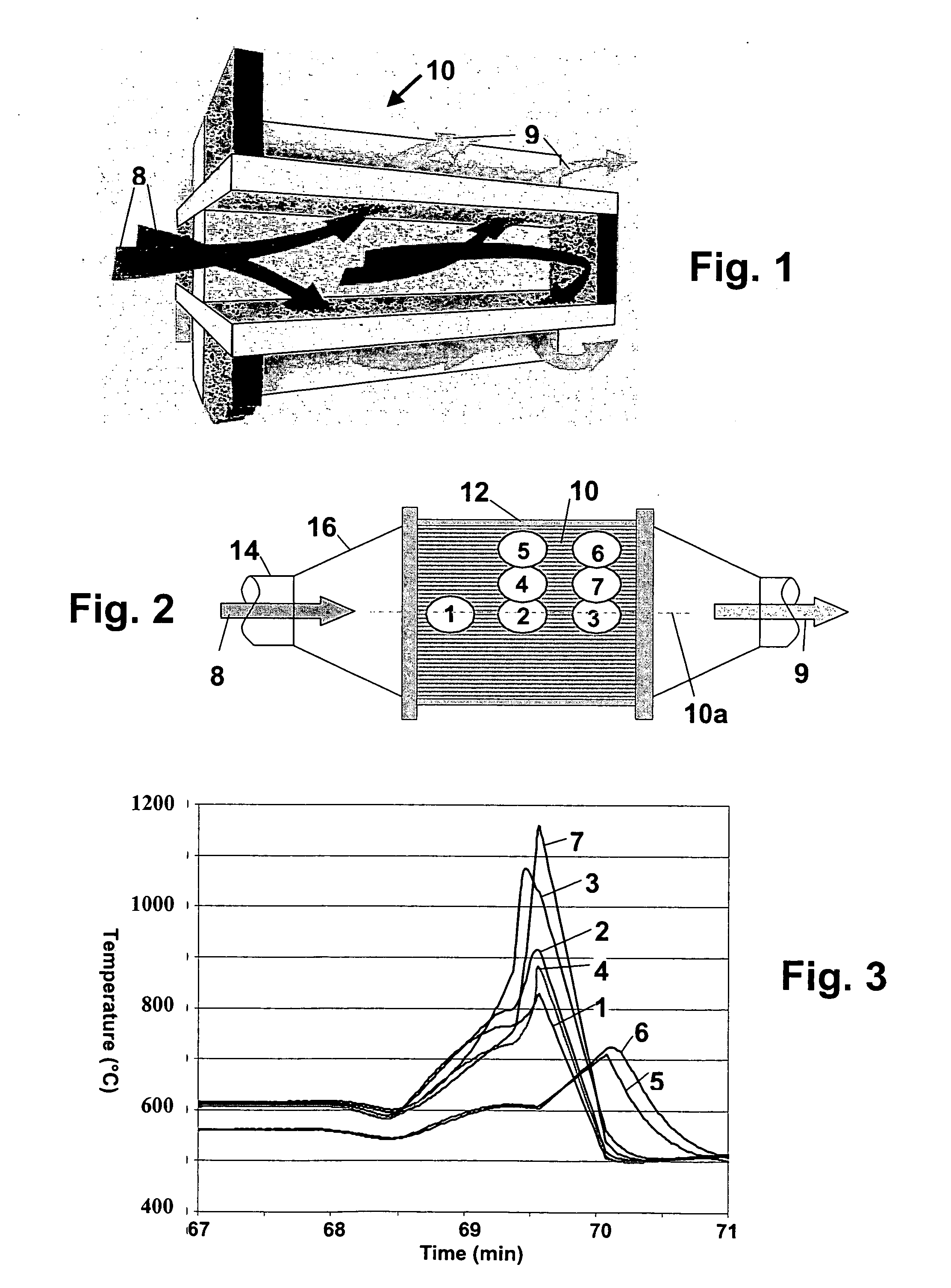
[0038] In a gas flow modeling experiment, a diesel particulate filter of porous ceramic composition, such as a cordierite wall-flow filter with alternate channels plugged in a checkerboard pattern, is modeled to generate a gas flow profile map for a simulated exhaust gas flowing therethrough. The evaluation is carried out for the case of a filter mounted in an enclosure provided with a conical gas inlet cone substantially as illustrated in FIG. 2 of the drawing.

[0039] The wall-flow filter selected for evaluation is in the shape of a right circular cylinder with flow channels parallel with the cylinder axis, the filter having a cylinder diameter of 22.86 cm and a cylinder length of 30.5 cm. The exhaust gas flow is delivered from an exhaust gas conduit of 10.16 cm diameter at an exhaust gas mass flow of 1100 kg / hr and at an exhaust gas temperature of 250° C.

[0040]FIG. 5 of the drawing plots the exhaust gas inlet flow profile developed under these flow conditions as ...

example 2

Fluidic Flow Control System

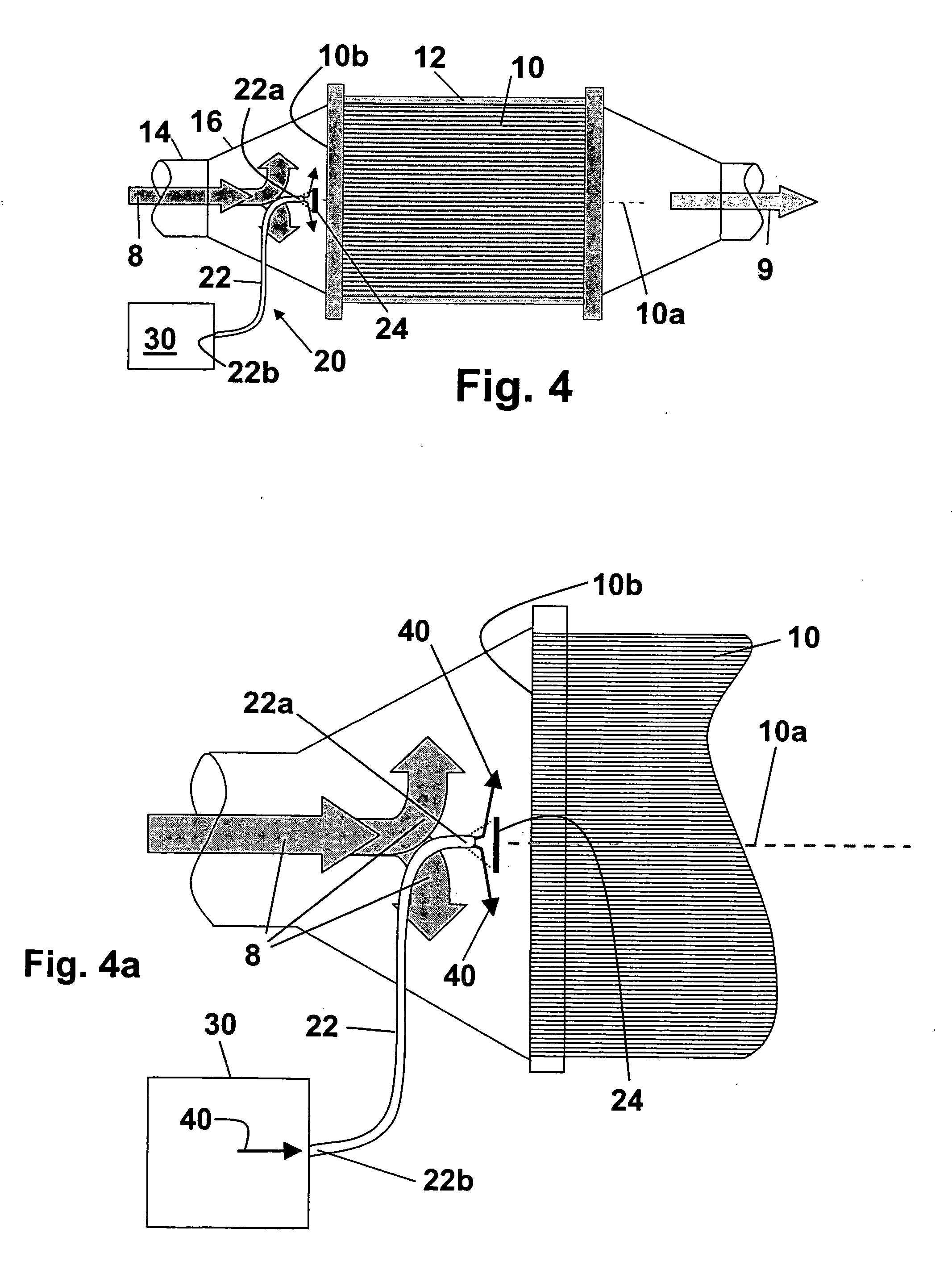
[0044] A prophetic example of the performance of a diesel engine exhaust system design such as illustrated in FIGS. 4-4a of the drawing is developed from the known flow profile characteristics of a porous ceramic wall flow filter such as disclosed above in Example 1. Data from the testing of fluidic flow control systems of the type previously used to control flow through honeycomb exhaust hydrocarbon adsorbers provides a basis from which qualitative plots of gas flow profile through wall flow filters under various diverter air flows can be generated.

[0045] The wall-flow filter used as a model for the evaluation is again in the shape of a right circular cylinder with flow channels parallel with the cylinder axis, the filter having a cylinder diameter of 22.86 cm and a cylinder length of 30.5 cm. The exhaust gas flow for inlet to this filter is delivered from an exhaust gas conduit of 10.16 cm diameter at an exhaust gas mass flow of 1100 kg / hr and at an ex...


PUM


Abstract

Apparatus and a method for controlling gas flow into a combustion engine exhaust gas filter e.g., to control filter temperatures during filter regeneration, comprising providing a fluidic exhaust stream diverter proximate to and centrally of the inlet face of the filter and activating the fluidic diverter to divert exhaust gas flow away from central filter portions toward peripheral filter portions.

Description

BACKGROUND OF THE INVENTION [0001] The present invention relates to systems for the removal of particulate material from diesel engine exhaust streams, and more particularly to exhaust systems utilizing porous ceramic diesel exhaust filters of honeycomb configuration to filter carbonaceous particulates (soot) from the exhaust stream prior to release into the atmosphere. [0002] Ceramic honeycomb particulate filters or traps have proven to be extremely efficient at removing carbon soot from the exhaust of diesel engines. Such filters are generally of so-called wall-flow design in that the soot is separated from the engine exhaust stream by capture on the porous channel walls of a honeycomb filter body as the exhaust gases are forced through those walls in traversing from an array of filter inlet channels to an adjacently interspersed array of filter outlet channels. Wall-flow filters can be designed to provide for nearly complete filtration of soot without significantly hindering the ...

Claims


Application Information

Patent Timeline
IPC IPC(8): F01N3/00F01N3/02F01N3/021F01N3/023F01N3/029F01N3/031F01N3/033F01N3/30F01N9/00F02B33/44F15D1/02
CPCF01N3/021F01N3/023F01N3/029F01N3/031F01N3/033F01N3/30Y02T10/47F01N2240/20F01N2330/06F01N2430/06F01N2430/08F01N2560/07F15D1/02F01N9/002Y02T10/40
Inventor PATIL, MALLANAGOUDA D.WILLIAMS, JIMMIE L.
Owner CORNING INC
Why Eureka
Try Eureka