Zone phase correcting lens and optical head device

a phase correction and optical head technology, applied in the field of zone phase correction lenses and optical head devices, can solve the problems of ineffective offset of the third-order spherical aberration and the fifth-order spherical aberration, the insensitivity of conventional lenses to wavelength fluctuations, and the inability to suitably concentrate laser beams on the recording surfaces of cd and dvd, etc., to achieve small aberration change caused by temperature and wavelength fluctuations, offset or reduce the change in spher

Inactive Publication Date: 2006-01-05
NIDEC NISSIN CORP
View PDF3 Cites 14 Cited by
  • Summary
  • Abstract
  • Description
  • Claims
  • Application Information

AI Technical Summary

Benefits of technology

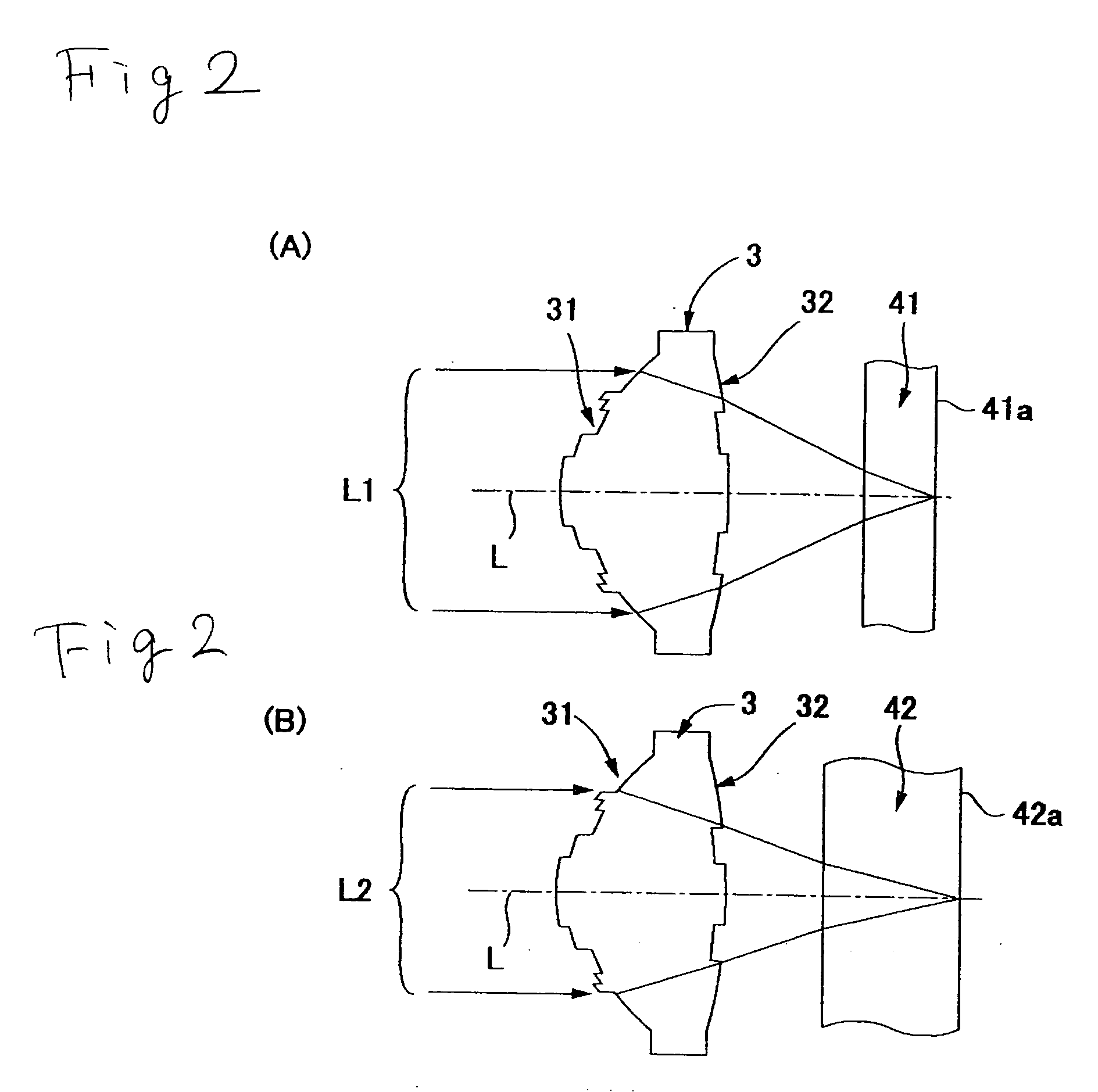
[0028] In the zone phase correcting lens according to the present invention, the lower limit (10×λ1)/(N1−1) has been set for the sum D of the adjacent step height measurements. Therefore, the adjacent step is large in comparison with the conventional zone phase correcting lens and therefore the zone phase correcting lens of the present invention is sensitive to wavelength fluctuations. More specifically, if the temperature rises, the wavelength of a laser beam tends to be longer and this change causes the proportion between the wavelength and the adjacent step height measurements to be out of balance and thereby shifts the spherical aberration. However, during the use at the wavelength λ1, the change in wavelength causes a spherical aberration in the positive direction. Therefore, it can offset or reduce the change in the spherical aberration in the minus direction caused by the change in temp

Problems solved by technology

Thus, the normal lens cannot suitably concentrate laser beams on the recording surfaces of the CD and the DVD.
Thus, the conventional lens is insensitive to wavelength fluctuations.
Therefore, it has a problem that, if t

Method used


Image

  • Zone phase correcting lens and optical head device
  • Zone phase correcting lens and optical head device
  • Zone phase correcting lens and optical head device

Examples


embodiment 1

[0111] Spacing: 1.75000

[0112] First surface [0113] Outside diameter=0.40000 [0114] Vertex step height measurement δ=0.00000 [0115] R=1.9409 [0116] k=0.000000E+00 [0117] A4=−0.103627E−01 [0118] Adjacent step height measurement d=−0.000134 [0119] Outside diameter=0.60000 [0120] Vertex step height measurement δ=0.00113 [0121] R=1.92920 [0122] k=0.000000E−01 [0123] A4=−0.125417E−01 [0124] Adjacent step height measurement d=−0.000878 [0125] Outside diameter=0.85000 [0126] Vertex step height measurement δ=0.00953 [0127] R=1.92316 [0128] k=0.000000E+00 [0129] A4=−0.122319E−01 [0130] Adjacent step height measurement d=−0.00139 [0131] Outside diameter=1.00000 [0132] Vertex step height measurement δ=0.01112 [0133] R=1.93640 [0134] k=−0.570271E+00 [0135] A4=0.162491E−02 [0136] Adjacent step height measurement d=0.00003 [0137] Outside diameter=1.30000 [0138] Vertex step height measurement δ=0.01030 [0139] R=1.94652 [0140] k=0.681358E−02 [0141] A4=−0.332210E−02 [0142] A6=−0.488377E−02 [0143] Ad...

embodiment 2

[0164] Spacing: 1.75000

[0165] First surface

[0166] Outside diameter=0.40000

[0167] Vertex step height measurement δ=0.00000

[0168] R=1.94109

[0169] k=0.000000E+00

[0170] A4=−0.115334E−01

[0171] Adjacent step height measurement d=−0.00136

[0172] Outside diameter=0.60000

[0173] Vertex step height measurement δ=0.00101

[0174] R=1.92168

[0175] k=0.000000E+00

[0176] A4=−0.149837E−01

[0177] Adjacent step height measurement d=−0.00880

[0178] Outside diameter=0.85000

[0179] Vertex step height measurement δ=0.00939

[0180] R=1.91953

[0181] k=0.000000E+00

[0182] A4=−0.127778E−01

[0183] Adjacent step height measurement d=−0.00136

[0184] Outside diameter=1.00000

[0185] Vertex step height measurement δ=0.00890

[0186] R=1.89958

[0187] k=−0.786108E+00

[0188] A4=0.261570E−02

[0189] Adjacent step height measurement d=−0.00008

[0190] Outside diameter=1.30000

[0191] Vertex step height measurement δ=0.01629

[0192] R=2.04682

[0193] k=−0.386395E−02

[0194] A4=0.734618E−02

[0195] A6=−0.566590E−02

[0196] Ad...


PUM


Abstract

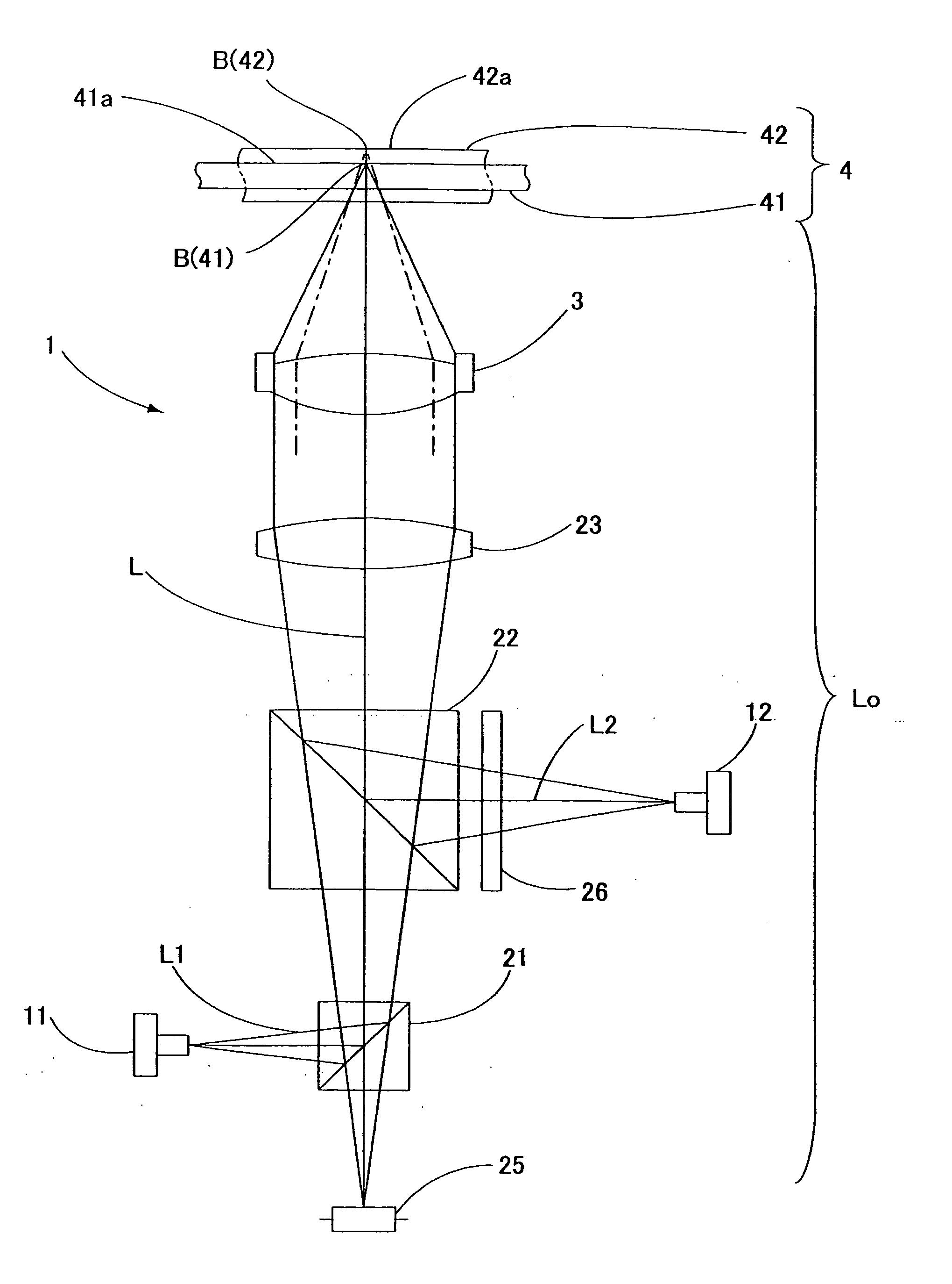
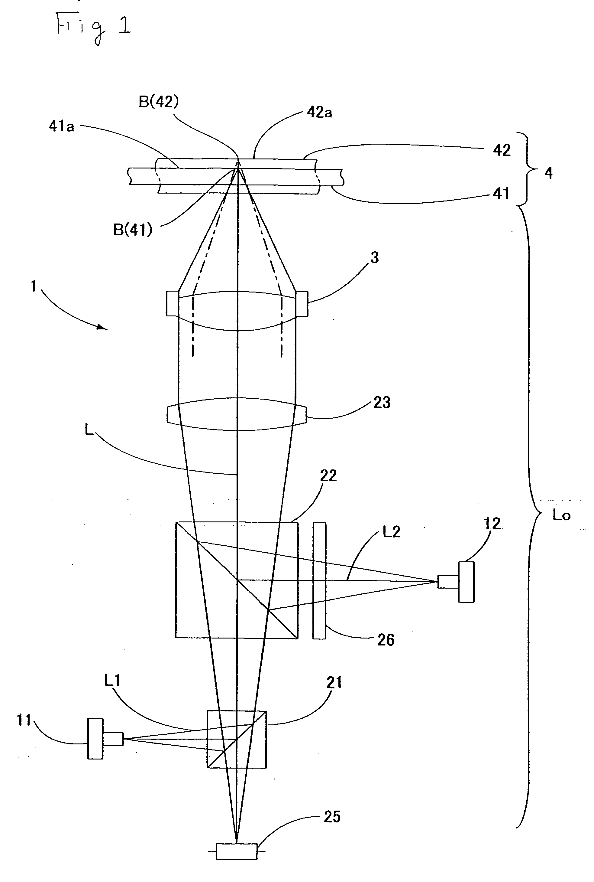
A zone phase correcting lens wherein a change in the third-order spherical aberration or the like is small in the case of a change in temperature and an optical head device having the zone phase correcting lens used as an objective lens. A minus sign is appended to the height measurement of a step formed so as to make the lens thickness in the optical axis thinner toward the outer region and a plus sign is appended to a step formed so as to make the lens thickness thicker toward the outer region. Supposing that D is an absolute value of the sum of the height measurements of the steps having the minus sign on the first surface and the second surface and E is an absolute value of the sum of the height measurements of the steps having the plus sign on the first surface and the second surface, a wavelength λ1 and a refractive index N1 of the lens for a first laser beam satisfy the following conditions:
10×λ1<{D×(N1−1)}<30×λ1
E<D.

Description

CROSS-REFERENCE TO RELATED APPLICATIONS [0001] This application claims priority of Japanese Application No. 2004-174496, filed Jun. 11, 2004 and Japanese Application No. 2005-117170, filed Apr. 14, 2005, the complete disclosures of which are hereby incorporated by reference. BACKGROUND OF THE INVENTION [0002] 1. Field of the Invention [0003] The present invention relates to a zone phase correcting lens capable of concentrating laser beams different in wavelength on recording layers of optical recording mediums such as a DVD and a CD different in board thickness and to an optical head device having the zone phase correcting lens used as an objective lens. [0004] 2. Related Background Art [0005] There are known optical recording mediums different in thickness of a transparent protective layer for protecting a recording surface or different in recording density like a CD, a DVD, and the like. A laser beam having a wavelength of approx. 655 nm is used for playing a DVD and a laser beam ...

Claims


Application Information

Patent Timeline
IPC IPC(8): G11B7/00
CPCG11B7/1367G11B2007/0006G11B7/13922G11B7/1374
Inventor OKAMURA, TETSURO
Owner NIDEC NISSIN CORP
Why Eureka
Try Eureka